

Drawings and documents
National Archives restored drawings: drawing
D. Gerrish's Patent Drawing for a Method of the Construction of Vessels


National Archives, Restored Patent Drawings (Record Group 241) · Full-size scan at the National Archives · Catalog record
Show the text on the drawing Hide (186 words)
Words on the drawing as machine-read by the National Archives; not checked. Useful mainly for searching.
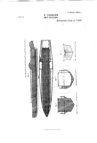
Sheet 1. CLASSEFICATION / DD o GERRISH / Patented 2 d gerly 1836 / 98T1- / DIVISION. / Constructions ressels / 9871X / with taning monny to show the linders / E'IG.2. / PTAN . FIGHT / 11 / CIN / Wheel / wheel / Scale / Fight / Fig. 3. / Eig 5. / Section forward of side Wheel / section showing the planting / Section Sterm Framing exactition work / Entig. / 17
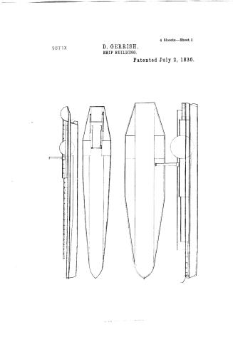
Sheet 2. GROUND PAAN OF BAAZ / Wheel leouse / 9.871.x / DIVISION / Wheel house / 0 9871x / Wheel house / IT / IT / II / 11 / If / II / Il / il / Il / Il / 11 / IT / IT / Long Frame I embress / crossFFames / D° / Kill / End view Section / Find view section / mind view Section / to / side view / scale lethpact / GROUNDPI.ANOHBAAT / Wheelhouse / tod / III / Wheel hous / de / OR / Find view section / to / on / side view
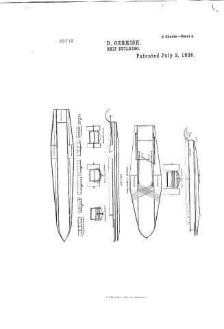
Sheet 3. Plan, sofect by 13 / Scale, one fourth inch to toots. / classIFICATION / 9871.1 / DIVISION. / 9871 X / Side Elevation / Plan. / Is / Vertical Section / Vertical Section / at.A / at B,B. / at c.c. / of / Waterline / Waterline- / M espect from a drawing / " Attach
Sheet 4. 9871.4 / DIVISION / 9871X / Scale: 1/12 In to fert / Eng / Scale 1/8 /n to toct. / Noto (eopid from a drawing not attached to the Patent
USPTO scan
The patent as scanned by the USPTO
-
 Page 1
-
 Page 2
-
 Page 3
-
 Page 4
-
 Page 5
-
 Page 6
-
 Page 7
-
 Page 8


U.S. Patent and Trademark Office · Google Patents
Show the transcription Hide (1,506 words)
Machine transcription (LightOnOCR) of the pages as scanned by the USPTO, most of them the handwritten copies made when the records were restored after the 1836 fire. Not checked; it can misread handwriting, so compare it with the scan.
Page 1.
9871X
4 Sheets—Sheet 1.
D. GERRISH.
SHIP BUILDING.
Patented July 2, 1836.

THE NORRIS BROTHERS CO. PHOTOGRAPHERS, WASHINGTON.
Page 2.
9871X
4 Sheets—Sheet 2.
D. GERRISH.
SHIP BUILDING.
Patented July 2, 1836.

Page 3.
9871X
D. GERRISH.
SHIP BUILDING.
Patented July 2, 1836.
4 Sheets—Sheet 3.

Page 4.
9871X
D. GERRISH.
SHIP BUILDING.
Patented July 2, 1836.
4 Sheets—Sheet 4.

THE MERRIS PETERS CO. PHOTO-LITHO., WASHINGTON, D.C.
Page 5.
9871
July 2, 1836
1,
Daniel Gerrish.
Letters Patent. Patented July 2, 1836.
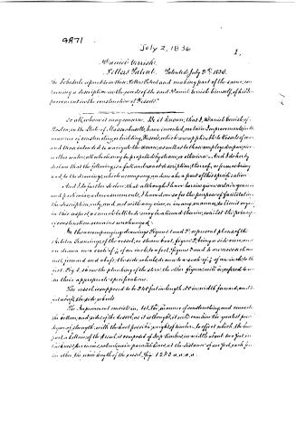
The Schedules referred to in these Letters Patent and making part of the same, containing a description in the words of the said Daniel Gerrish himself, of his improvement in the construction of Vessels.
To all, whom it may concern. Be it known, that I, Daniel Gerrish, of Boston, in the State of Massachusetts, have invented certain Improvements in the manner of constructing building Vessels, which are applicable to Vessels of war, and those intended to navigate the Ocean, as well as to those employed upon rivers and other waters, all which may be propelled by steam, or otherwise. And I do hereby declare that the following is a full and exact description thereof, as referred being made to the drawings, which accompany and make a part of this specification.
And I do further declare, that although I have herein given certain general and particular measurements, I have done so for the purpose of facilitating the description only, and not with any view, or in any manner, to limit myself in this respect, as much latitude may be allowed therein, whilst the principle of construction remains unchanged.
In the accompanying drawings Figures 1 and 2, represent plans of the skeleton framing of the vessel, or steam boat, figure 2, being a side view, and are drawn on a scale of 1/4 of an inch to a foot; figures 3 and 4 are cross sections, incl. forward and abaft; the side wheels, drawn to a scale of 1/2 of an inch to the foot. Fig. 5, shows the planing of the stern; the other figures will be referred to in their appropriate specifications.
The vessel is supposed to be 240 feet in length, 30 in width forward, and 25 feet abaft the side wheels.
The improvement consists in, 1st, the manner of constructing and connecting the bottom and sides of the vessel, as it is thought, it will combine the greatest possible degree of strength with the least possible weight of timber. To effect which, the lower part, or bottom of the vessel, is composed of deep timbers, in width about two feet, in thickness five inches, extending in parallel lines, at the distance of one foot, each from the other, the entire length of the vessel, figs. 1, 2, 3, 4, 5, 6, 7, 8, 9, 10, 11, 12, 13, 14, 15, 16, 17, 18, 19, 20, 21, 22, 23, 24, 25, 26, 27, 28, 29, 30, 31, 32, 33, 34, 35, 36, 37, 38, 39, 40, 41, 42, 43, 44, 45, 46, 47, 48, 49, 50, 51, 52, 53, 54, 55, 56, 57, 58, 59, 60, 61, 62, 63, 64, 65, 66, 67, 68, 69, 70, 71, 72, 73, 74, 75, 76, 77, 78, 79, 80, 81, 82, 83, 84, 85, 86, 87, 88, 89, 90, 91, 92, 93, 94, 95, 96, 97, 98, 99, 100, 101, 102, 103, 104, 105, 106, 107, 108, 109, 110, 111, 112, 113, 114, 115, 116, 117, 118, 119, 120, 121, 122, 123, 124, 125, 126, 127, 128, 129, 130, 131, 132, 133, 134, 135, 136, 137, 138, 139, 140, 141, 142, 143, 144, 145, 146, 147, 148, 149, 150, 151, 152, 153, 154, 155, 156, 157, 158, 159, 160, 161, 162, 163, 164, 165, 166, 167, 168, 169, 170, 171, 172, 173, 174, 175, 176, 177, 178, 179, 180, 181, 182, 183, 184, 185, 186, 187, 188, 189, 190, 191, 192, 193, 194, 195, 196, 197, 198, 199, 200, 201, 202, 203, 204, 205, 206, 207, 208, 209, 210, 211, 212, 213, 214, 215, 216, 217, 218, 219, 220, 221, 222, 223, 224, 225, 226, 227, 228, 229, 230, 231, 232, 233, 234, 235, 236, 237, 238, 239, 240.
Page 6.
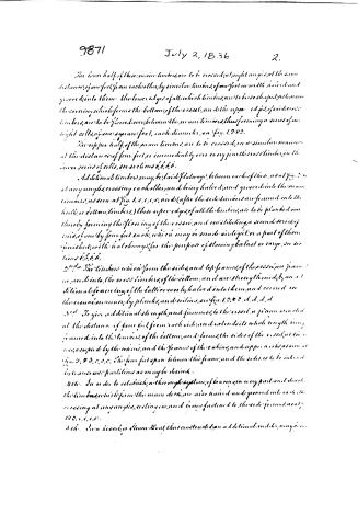
The lower half of these main timbers are to be crossed at right angles, at the same distance, of one foot, from each other, by similar timbers, of one foot in width, joined and grooved into them. The lower edges of all which timbers are to be so shaped as to cover the covering which forms the bottom of the vessel, and the upper edges of said lower timbers are to be flared over, between the main timbers, thus forming a series of right angles, of one square foot, each diameter, as fig. 1, 2, 3.
The upper half of the main timbers are to be crossed, in a similar manner, at the distance of four feet, or immediately over every fourth cross timber, in the lower series of cells, see sections b, b, b, b.
Additional timbers may be laid flatways, between each of these, as at fig. 2, at any angles, crossing each other, and being halved and grooved into the main timbers, as seen at fig. 1, 2, 3, 4, 5, and 6 (after the side timbers are framed into the hull or bottom timbers,) these upper edges of all the timbers are to be planed over, thereby forming the flooring of the vessel, and constituting a second series of cells, of one by four feet each, which may be made air-tight, or a part of them finished with hatchways for the purpose of stowing ballast or cargo, see sections c, c, c, c.
2nd. The timbers which form the sides and top frames of the vessel are framed in, and into the cross timbers of the bottom, and are strengthened by an additional framing of the battens or baulks, halved into them, and secured in the same manner, by planks and ceiling, see fig. 1, 2, 3, 4, 5, 6, 7, 8, 9, 10, 11, 12, 13, 14, 15, 16, 17, 18, 19, 20, 21, 22, 23, 24, 25, 26, 27, 28, 29, 30, 31, 32, 33, 34, 35, 36, 37, 38, 39, 40, 41, 42, 43, 44, 45, 46, 47, 48, 49, 50, 51, 52, 53, 54, 55, 56, 57, 58, 59, 60, 61, 62, 63, 64, 65, 66, 67, 68, 69, 70, 71, 72, 73, 74, 75, 76, 77, 78, 79, 80, 81, 82, 83, 84, 85, 86, 87, 88, 89, 90, 91, 92, 93, 94, 95, 96, 97, 98, 99, 100.
3rd. To give additional strength and firmness to the vessel, a frame is erected at the distance of four feet from each side, and extends its whole length, being joined into the timbers of the bottom, and forms the sides of the vessel, at the same time occupied by the cabins, and the frames of the cabins, and upper works, as seen at fig. 2, 3, 4, 5, 6, 7, 8, 9, 10, 11, 12, 13, 14, 15, 16, 17, 18, 19, 20, 21, 22, 23, 24, 25, 26, 27, 28, 29, 30, 31, 32, 33, 34, 35, 36, 37, 38, 39, 40, 41, 42, 43, 44, 45, 46, 47, 48, 49, 50, 51, 52, 53, 54, 55, 56, 57, 58, 59, 60, 61, 62, 63, 64, 65, 66, 67, 68, 69, 70, 71, 72, 73, 74, 75, 76, 77, 78, 79, 80, 81, 82, 83, 84, 85, 86, 87, 88, 89, 90, 91, 92, 93, 94, 95, 96, 97, 98, 99, 100.
4th. In order to establish a thorough system of bracing in every part, and direct the timbers which form the main deck, are also nailed and grooved into each other, crossing at any angles, as they are, and being fastened to the side frames, as at fig. 1, 2, 3, 4, 5, 6, 7, 8, 9, 10, 11, 12, 13, 14, 15, 16, 17, 18, 19, 20, 21, 22, 23, 24, 25, 26, 27, 28, 29, 30, 31, 32, 33, 34, 35, 36, 37, 38, 39, 40, 41, 42, 43, 44, 45, 46, 47, 48, 49, 50, 51, 52, 53, 54, 55, 56, 57, 58, 59, 60, 61, 62, 63, 64, 65, 66, 67, 68, 69, 70, 71, 72, 73, 74, 75, 76, 77, 78, 79, 80, 81, 82, 83, 84, 85, 86, 87, 88, 89, 90, 91, 92, 93, 94, 95, 96, 97, 98, 99, 100.
5th. In a vessel of steam power, thus constructed, an additional number may be
Page 7.
9871
July 2, 1836
3.
a vertical, iron, or brass, on a shaft, which descends through an open trunk, or well, from the deck to the water, which will when required, secure a more perfect control over the direction of the vessel, and may be preserved from injury by being more or less immersed within the recesses formed for that purpose, as seen at fig. 1, f, f.
6th. In steam vessels, designed for sea service, I propose to place a part of the paddle Wheels, in a recess, of four feet, formed in the sides of the vessel, allowing them to project six feet, they being ten feet wide, and twenty four in diameter, as fig. 1, g, g. The inner c, c, show the wheel, g, g, and ff, the sides of the vessel.
I propose also to place an additional wheel, in the stern, occupying the same width of that part of the vessel, say 20 feet, in length, and 22 feet in diameter, as at fig. 1, h, h.
Figs. 6 & 7, show the location of two horizontal Engines, within the gunwale, and each on a line, and connected by a shaft, or axle, with the main, or side, or paddle wheel, and also by another shaft, or axle, to the crank, or end of the stern, or wheel shaft, this last, named shaft, or axle, being connected, to or with the cross head, by a guide rod, i, i, i, i.
The same wheel, being thus connected, with the two cranks, on the outside at right angles with the two cranks, of the other side, j, j, all the wheels, will be uniform in acting, the full action of the engines, viz. as much so while one of the cranks is passing their head center, as at any other part, or point, of the revolution. And also, when by the motion of the waves, either of the three wheels, has little or no hold upon the water, the whole power of both Engines will still be exerted upon the immersed wheels.
7th. I propose, when it is also able, to place the chimney, or smoke pipe, horizontally, along the sides, or gunwales of the vessel, allowing the smoke to escape, into the air, by the stern, or side wheels, the action of which will be calculated to promote the discharge of the smoke, as fig. 7, k, k.
8th. I intend sometimes, to form the covering of the bottom, instead of sheet iron, or other metal, instead of plank, which will secure, most of the benefits arising from iron, but which, the vessel will be lighter, and, much more secure, from danger in case of leak or accident, as the water would be confined to a comparatively small number of joints. When the vessel is intended to navigate shallow waters, the form of the bottom
Page 8.
9871
July 2, 1836
4
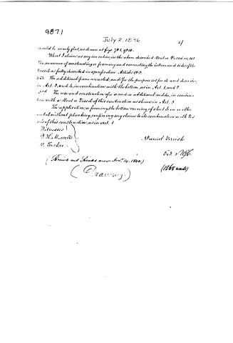
should be nearly flat, as shown at figs. 7, 8, 9, 10.
What I claim as my invention, in the above described Boat or Vessel is, 1st
The manner of constructing or framing and connecting the bottom and sides of the Vessel as fully described in specification. Articles 1, 2, 3.
2nd. The additional frame ascribed, and for the purpose set for the and described in Art. 3, and 4, in combination with the bottom, as in Art. 1, and 2.
3rd. The manner and construction of a second or additional ladder, in combination with a Boat or Vessel of this construction as shown in Art. 5.
The application of forming the bottom covering of sheet Iron or other metal without planking, confining my claim to its combination with the sides of this construction, as in Art. 1.
Witnesses
J. H. H. H.
W. Tucker
Daniel Harris
Ex. 2. 2/6.
(1568 words)
(Proceeds and Patent issued April 14, 1840.)
(Drawing)
Published accounts: journal notice
Notice in the monthly list of patents
Journal of the Franklin Institute, new ser., vol. 18 (1836), p. 359 · View the page
583. Vessels, construction of.---Daniel Gerrish, Boston, Mass.
About this record
- Patentee
- the Journal of the Franklin Institute, Journal
- Date
- the Name and Date index of patents, USPTO records, Jim Shaw's X-patent list
- Invention
- the Name and Date index of patents
- Listed in
- the Name and Date index of patents, USPTO records, Jim Shaw's X-patent list, the Journal of the Franklin Institute, Burke's List of Patents (1847)
- The patentee's full name comes from the Franklin Institute's journal.
- Burke's 1847 Patent Office list gives the same patent.