

Drawings and documents
USPTO scan
The patent as scanned by the USPTO
-
 Page 1
-
 Page 2
-
 Page 3
-
 Page 4
-
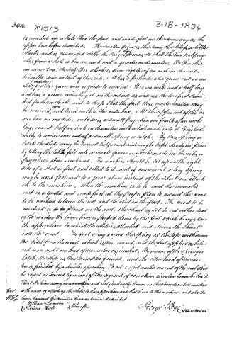 Page 5


U.S. Patent and Trademark Office · Google Patents
Show the transcription Hide (1,886 words)
Machine transcription (LightOnOCR) of the pages as scanned by the USPTO, most of them the handwritten copies made when the records were restored after the 1836 fire. Not checked; it can misread handwriting, so compare it with the scan.
Page 1.
UNITED STATES PATENT OFFICE
PTO – BOYERS, PA DUTY STATION
PAGE NOT AVAILABLE
PATENT NUMBER X9513 FOR THE ISSUE DATE 3/18/1836 HAS BEEN SCANNED/LOADED, BUT WITH MISSING PAGE(S). UPON RECEIPT OF THE MISSING PAGE(S), THE ENTIRE DOCUMENT WILL BE RESCANNED. THIS NOTICE IS FOR THE MISSING PAGE CONTAINING:
Missing All Drawings
DATA CONVERSION OPERATION
BOYERS, PA
Page 2.
X9513
3-18-1836
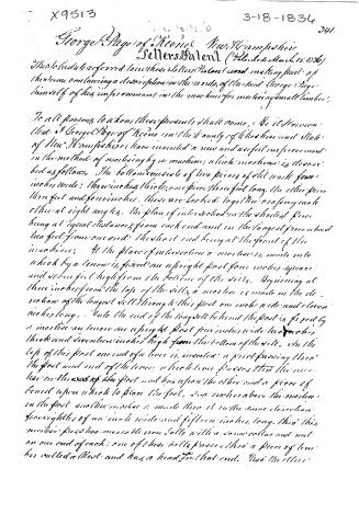
341.
George Page of Keene, New Hampshire
Sellers Patent (Patented March 18, 1836)
This schedule referred to in the Letters Patent and making part of the terms containing a description in the words of the said George Page himself of his improvement in the machine for mortising small timber.
To all persons to whom these presents shall come, (Be it known) that I George Page of Keene in the County of Cheshire and State of New Hampshire have invented a new and useful improvement in the method of mortising by a machine, which machine is described as follows. The bottom consists of two pieces of old work four inches wide; three inches thick, one piece three feet long, the other piece three feet and four inches, these are locked together so as to form each other at right angles, the plan of intersection in the shortest piece being at equal distances from each end and in the longest piece about two feet from one end, the short end being at the front of the machine. At the place of intersection a mortise is made into which by a tenon is fixed an upright post four inches square and seven feet high from the bottom of the well. Beginning at three inches from the top of the well, a mortise is made in the direction of the longest well through this post one inch wide and eleven inches long. Into the end of the longest well behind the post is fixed by a mortise an tenon an upright post four inches wide, two inches thick and seventeen inches high from the bottom of the well. On the top of this post one end of a lever is inserted; a pivot passing through the post and end of the lever, which lever passes through the mortise in the end of the post and has upon the other end a piece of board upon which to place the foot, six inches above the mortise in the post another mortise is made through it in the same direction four eighths of an inch wide and fifteen inches long, through this mortise pass two movable iron bolts with a screw collar and nut on one end of each; one of these bolts passes through a piece of timber called a Rest and has a head on that end. Two the other
Page 3.
342. X9513 3-18-1836
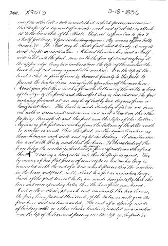
inside the oblique well a hole is made third which passes unison in the shape of a segment of a circle, each end of which is attached to the lower side of the chest. This rod is from two to two and a half feet long, and four inches long square. By means of two bolts screws, etc. The chest may be made fast and steady at any desired height or inclination. A board three inches and a half wide is let into the post, even with the face of it and crossing it, the upper edge being two inches above the top of the mortise, the board being set away against the mortise. Near the top of the board a slot or piece of iron is screwed firmly to the post to prevent the lumber from swinging the operation of the machine.
About four feet three inches from the bottom of the well, a brace of the size of the post and three feet long is inserted in the post inclining forwards at an angle of nearly two degrees from a horizontal line. This brace is made steady by a girl or an iron rod with a screw and nut on one end and a head on the other passing through it and the post near the top of the latter.
Beginning five feet nine inches from the bottom of the well and the mortise is made thru the post, in the same direction as those below, an inch wide and eight inches long. A similar mortise used with this is made thru the brace. To the outside of the brace below the mortise is fastened by two pieces of cast iron shaped thus: A having a horizontal hole thru the projecting end. This by means of two flat pieces of iron eight or ten inches long is connected with the end of a lever which passes thru the mortise in the brace and post, and is about two feet nine inches long. Back of the post several holes are made horizontally thru this lever and corresponding holes thru the lever first mentioned. A rod with a clevis at each end connects the two levers, the pins being passed thru each of the holes, as will give the pure horse and motion wanted. The end of a spring made of hickory pole or other elastic timber is inserted in a mortise near the top of the brace and passing over the top of the post is
Page 4.
X9513
3-18-1834 343.
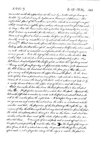
connected with the upper lever at the end by a leather strap having a buckle by which it may be tightened or loosened at pleasure. An important part of the machine is a slide which is a rod of iron put 1 sheet round seven eighths of an inch in diameter and two feet seven inches long. Into the lower end a hole is drilled longitudinally two inches deep to serve as a socket for the chisel. About two inches from the lower end and in front a hole or mortise half an inch long and three sixteenthths wide is made in it by which the chisel may be keyed or driven. About two inches from the lower end on one side a small hole is also drilled through it, and four and a half inches above another, into which is inserted and fastened the bent ends of a square iron guide. Into the top of the slide a hole is also drilled two inches deep into which a bolt is inserted and fastened by a pin. This bolt has a head shaped like half a globe or ball the top being round and having with pins projecting at opposite sides called a yoke surrounding the bolt between the head and the slide the pins going thro' the end of a rivet which passes over the upper lever near the post. To the lower side of this lever is fastened an iron plate, into which a hole is countersunk to receive the head of the bolt, which is drawn up into it by a wedge driven between the upper side of the lever and the rivet.
About two inches below this lever the slide passes thro' a box shaped thus $\mathcal{B}$ . The projection is inserted in a hole thro' the post. Against this hole on the left side a mortise is made into the post and a small hole is bored to the mortise from the right side. A holdfast being a screw with an eye on one end and a thumb nut on the other is introduced into the mortise and hole. The projection of the box passing through the eye. By means of this the slide may be set at any desired distance from the post. The slide then passes down through a hole in the brace, and about two inches above the lower end of the slide it passes thro' another box constructed thus. It consists of several parts and is made of cast iron. One part is shaped thus $\mathcal{F}$ and the other thus $\mathcal{F}$ . The length of the large piece from a to b is about six inches, the general thickness three fourths of an inch. a is a projection rising at the edges a and b. The part c?
Page 5.
344 X9513 3-18-1836
is inserted in a hole thro' the foot, and made fast in the same way as the upper box before described. The smaller piece is the same thickness, a little shorter and is connected with the larger by screws so that the two half circles form a hole or box an inch and a quarter in diameter. Within this is an inner box: the hole thro' which is seven eighths of an inch in diameter being the same as that of the slide. It has a perpendicular groove cut on one side for the square wire or guide to run in. It is an inch and a half long and has a groove encircling it on the outside as wide as the two first described parts are thick, and so deep that the foot thus made smaller may be received and turn within the outer box. At the upper end of this inner box on one side, outside is a small projection one fourth of an inch long, round half an inch in diameter with a hole made into it longitudinally to receive one end of a small spring or latch. By this spring or latch the slide may be turned half round and may be kept steady in place by letting the latch fall into a small groove or notch made in the ribs or projections above mentioned. The machine should be set up on the right side of a stud or post and bolted to it, and if convenient a long spring may be used fastened to a joint above instead of the short one attached to the machine. When the machine is to be used the movable rest is adjusted and made fast at the proper place to admit the wood to be marked between the rest and the sled on the post. The wood to be marked is placed on the rest, the chisel is set to cut either head of the machine the lower lever is dropped down by the foot which brings down the upper lever to which the slide is attached and driving the chisel into the wood. The foot being raised the spring at the top withdraws the sled from the wood, which is then moved, and the foot applied as before and so on until one head of the machine is finished. By means of the spring or latch, the slide is then turned half round, and the other head of the machine is finished by a similar operation. The tool marks on one end of the wood should be raised or covered by means of the segment of a circle or circular brace below.
That I claim as my own invention and not previously known in the above described machine is the mode of attaching the slide to the upper box and that lever to the machine, and also the lower box and the circular brace as herein described.
William Cameron & Helena Hale 3 Minutes
George Hage 182.0 00000
Published accounts: journal notice
Notice in the monthly list of patents
Journal of the Franklin Institute, new ser., vol. 17 (1836), p. 438 · View the page
209. Morticing machine. George Page, Keene, N. H.
Published accounts: journal notice
Notice in the monthly list of patents, with remarks
Journal of the Franklin Institute, new ser., vol. 18 (1836), p. 390 · View the page
69. For a Mortising machine; George Page, Keene, Cheshire county, New Hampshire, March 18.
Remarks. The general resemblance in principle between this and some mortising machines which have preceded it, is such as to leave little apparent room for a claim, and it does not occupy a large space, being to "the mode of attaching the slide to the upper lever and that lever to the machine; and also the lower box, and circular brace as described." We shall not take time to describe these particulars, but have no doubt that they are equally good with other modes of attaining the same end, and that the machine, if well made, will work well.
About this record
- Patentee
- DATAMP
- Date
- the Name and Date index of patents, DATAMP, USPTO records
- Invention
- DATAMP
- Listed in
- the Name and Date index of patents, DATAMP, USPTO records, Jim Shaw's X-patent list, the Journal of the Franklin Institute, Burke's List of Patents (1847)
- Burke's 1847 Patent Office list gives the same patent.