

Drawings and documents
USPTO scan
The patent as scanned by the USPTO
-
 Page 1
-
 Page 2
-
 Page 3


U.S. Patent and Trademark Office · Google Patents
Show the transcription Hide (918 words)
Machine transcription (LightOnOCR) of the pages as scanned by the USPTO, most of them the handwritten copies made when the records were restored after the 1836 fire. Not checked; it can misread handwriting, so compare it with the scan.
Page 1.
8833X
J. L. Dutton,
Sawing Stone.
Patented May 22, 1835.

AM. PHOTO-LITHO. CO. N.Y. (OSBORNE'S PROCESS)
Page 2.
May 22, 1835
Joseph L. Dutton
Letter Patent 8833X
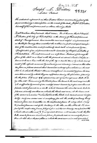
The schedule referred to in these Letters Patent and making part of the same containing a description in the words of the said Joseph L. Dutton himself of his improvement in Stone Sawing Mills
To all to whom these presents shall come: Be it known that I Joseph L. Dutton of the City of Philadelphia in the County of Philadelphia and State of Pennsylvania have invented new and useful improvements in Mills for sawing stone and that the within is a full and exact description of the construction and operation of said mill as improved by me.
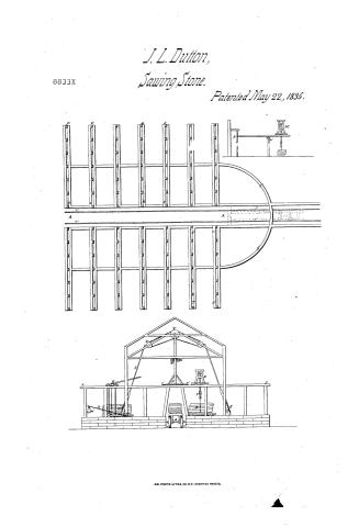
Specification of an improved saw mill invented by Joseph L. Dutton of Philadelphia. The improvements are as follows. Instead of placing the floor of the Mill on a level with the ground as usual I raise it so far above as to be on a line with the bed of the log or marble teams by which means most of the expense incurred by unloading and reloading is saved on this elevated floor we place several short transverse railways upon which run the cars B, C, to which the blocks & stone are transferred immediately from the common teams and by which they are supported during the operation of sawing.
In the plan P, P and Q, Q represent one set of railways and R, R, S, S, &c other sets. The removing the blocks from the teams to the railway cars B, C is effected by means of an endless screw turned by proper cranks and friction work framed on a car E, which traverses the elevated rails R, R, &c placed directly over those on which the block cars run. At the lower end of the screw is a swivel V which allows the block to be turned round horizontally: only one screw car is necessary for all the sets of railways being carried from one to another on the suspended frame D, along which it may be pushed from one end of the building to the other on the rollers H, H. The lower part of this suspended frame plays a few inches vertically on a pivot at W, which allows either end V, V as required to come into contact with the floor I, I, so as to form an inclined plane for greater ease in carrying the frame E on it. H, H show the saw plates in which the saws move in a nearly vertical direction.
Page 3.
direction (which motion has already been patented and has been found a great
ly preferable to the horizontal owing to the ease of supplying the same and also
of the diminished friction on the saw blades which are delivered from the weight
of the block as it separates into slabs) I. is the pitman through which motion
is communicated to the saws by the wheels and bands X.Y. which are operated
on by any convenient prime mover. The block of stone C is kept constantly pressed against the saw by means of the lever D, at the end of which
is hung a weight W, of proper size for the purpose which may be moved back
wards and forwards as on a common steel yard. Near the other end is a ratchet
et which permits the lever to be raised without causing the pinion O to re-
volve, but which in descending catches the teeth of the pinion which in
turn engages those of a rack bar placed under the centre of the block car
and thus maintains a continual pressure of the block against the saw
blade. To prevent this pressure from becoming at any time too great each
saw slide is furnished with a strong wooden spring K, which by yielding
when the weight W operates too strongly pressing a proper degree of pressure.
The stiffness of this spring must of course be capable of adjustment. For ease
of moving blocks and commanding a large space of yard I employ a crane
whose turning point may be at G as usual but whose stay traverses (either
by means of rollers at N, or in any other manner convenient may direct)
railways of semicircular form which may be arranged as shown in plan
by S.S. and by the dotted lines or otherwise. On the top of the crane travels
a screw car (like that at B) for lifting blocks from the ground and placing
them either in another part of the yard upon a railway car by which
they may be carried into or out of the mill on the railway R.R. of common
construction. By this crane any extent of yard may be commanded.
What I claim as new and for which I claim an exclusive right are the
raising of the mill floor as above described, the traversing car B, the application
of the upper car B to saw mills, the car G, the crane as better applied
to saw mills or for any other purpose and the regulating spring of the saw
slide
Witnesses
Simon Mason
William Wilson
Joseph L. Dutton
9/15 W7
Drawing
Published accounts: journal notice
Notice in the monthly list of patents, with remarks
Journal of the Franklin Institute, new ser., vol. 16 (1835), p. 397 · View the page
It will be readily seen that the coupling bar, or jointed rod, by which the car is attached to a locomotive, if attached to it at a point considerably above that by which it is attached to the car, will tend to lift the latter, and to draw down the former, and thus to increase the adhesion of its hind wheels. 35. For an improvement in Mills for Sawing Stone; Joseph L. Dutton, city of Philadelphia, May 22.
Remarks. This patent is taken for the particular construction of the building in which the sawing is to be effected. In the first place, the floor of the mill is to be raised to such a height from the ground "as to be on a line with the bed of the log or marble teams, by which means most of the expense incurred by unloading, and reloading, is saved." On this elevated floor are placed several short transverse railways, upon which run cars to which the blocks of stone are transferred, immediately from the common teams, and by which they are supported during the operation of sawing. Above the before mentioned railways, the frame work of the building supports other railways upon which also there is a car furnished with a screw, by means of a chain dependent from which, a block of marble may be suspended and transferred to any part of the mill where it may be wanted. A crane is likewise constructed, which sustains a car similar to that last described, for aiding in the transfer of the stone from one part of the building to another. The arm of this crane is supported upon friction wheels, running upon a suitable curved way, erected for that purpose. "I claim an exclusive right to the raising of the mill floor, as above described. The traversing car. The application of the upper car to saw mills. The crane whether applied to saw mills, or for any other purpose; and the regulating spring of the saw slides." We think that the foregoing claim is very susceptible of improvement. The mere raising of the floor, for the purpose pointed out, we do not think new in saw mills, for we err greatly if we have not seen, in Philadelphia itself, a mill, for sawing mahogany, with the floor so raised " as to be on a line with the bed of the log" carriage. Nothing is said about any novelty in the traversing car which is to receive the stone, nor do the upper cars differ from such as have been used for raising and transferring loads, for other purposes. The crane is claimed, "whether applied to saw mills, or for other purposes," now this assuredly does not mean a crane generally, yet we are not told in what particular this crane differs from others; a thing that should not be left to be inferred, but which ought to have been particularly specified. The fact is that the novelty and utility of the structure consist not so much in the formation of its individual parts, as in the general arrangement and combination of the whole, by which it is adapted to the attainment of the object proposed, and upon this the claim to invention must mainly rest.
Published accounts: journal notice
Notice in the monthly list of patents (listed with a different spelling or date)
Journal of the Franklin Institute, new ser., vol. 16 (1835), p. 71 · View the page
Stone sawing mills. Joseph L. Dutton, city of Philadelphia,
About this record
- Patentee
- DATAMP
- Date
- the Name and Date index of patents, DATAMP, USPTO records
- Invention
- DATAMP
- Listed in
- the Name and Date index of patents, DATAMP, USPTO records, Jim Shaw's X-patent list, the Journal of the Franklin Institute, the Journal of the Franklin Institute, Journal
- Also listed in a contemporary journal or list under a different spelling or date; the record shown follows the standard lists.