

Drawings and documents
USPTO scan
The patent as scanned by the USPTO
-
 Page 1
-
 Page 2
-
 Page 3
-
 Page 4
-
 Page 5
-
 Page 6


U.S. Patent and Trademark Office · Google Patents
Show the transcription Hide (2,068 words)
Machine transcription (LightOnOCR) of the pages as scanned by the USPTO, most of them the handwritten copies made when the records were restored after the 1836 fire. Not checked; it can misread handwriting, so compare it with the scan.
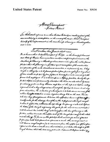
Page 2.
United States Patent
Patent No.: X9134
Moses Davenport
Letters Patent
The Schedule referred to in these Letters Patent (and making part of the same) containing a description in the words of the said Moses Davenport himself of his improvement in the machine for cleaning or threshing clover seed or rice.
To all to whom these Presents shall come
Be it known that Moses Davenport of Philips in the County of Somerset and State of Maine have invented a new (and) useful improvement in the Machine for Cleaning or threshing clover seed or rice upon the rubber principle (and that the following is a full (and) exact description of the construction (and operation of the said Machine as invented or improved by me. A long trough or oblong box is to be formed of about from five to eight feet long about fifteen inches deep (and by from fifteen to twenty four wide according to the power to be employed) it is to be set up in a slanting position having the upper (and) sloped end permanently closed (and the lower one also closed by means of a sliding gate working between cross bars, at the top and bottom acting as guides, with a key average at each end of the top bars to secure it, at any given elevation, the intention of which gate is to hold down one end of the rubber hereafter described in order to give a strong bite on the seed. There are to be two long openings made between the upper (and) lower cross bars sufficiently wide for the sliding bars of the rubber to pass and also high enough to admit of friction rollers on the top thereof. An opening is also to be left in the bottom of the trough adjoining this gate for the seed to run out at, (and will be about ten inches long, extending from the line of bearing in the friction rollers towards the upper end of the trough (and may be the whole width thereof. The lower rubber plate (which consists of a series of metal perforated with holes punched upwards or such other arrangement as will leave a rough surface) is to commence from the upper end of this opening (and is let down a small some short distance just below the surface of the trough bottom that the seed may fall into it (and will be from one (and) a half
Page 3.
United States Patent
Patent No.: X9134
half to three feet long running up the trough. Above this rests the upper rubber of the same dimensions hinging the two rough sides in contact, and is secured to the rubber frame, which bears on the top of it. This frame consists of two long sliding bars say about two thirds of the length of the trough which are set up edge wise & their lower ends pass through the openings already described in the lower gate, the remainder lies along the bottom of the trough having the upper rubber secured to them & the balance of their length is formed into a kind of rack, consisting of narrow slips say from four to six inches deep & of the same length as the width of the trough to be secured to the under edge of the sliding bars at intervals of about six inches apart, (at the upper end & on the top of these sliding bars is fastened on a heavy weight in the form of a head block or box, of say about two feet in length & the other dimensions to fit the trough, it may be if a box, filled with weights during the operation and then removed for the transportation of the machine elsewhere, as three hundred weight nearly may be requisite in order to effect the purpose that of giving leverage or bearing enough on the rubber from the fulcrum at the other end of the sliding bars through the lower gate, to cleanse the seed. The upper end of this box has a row of teeth at the bottom to descend about the same depth as the narrow slips of the rack, (and the top of this same end has a projection with a slit in it at each side, in order to receive therein an arm to each (turning upon a pin or pivot) of about fifteen inches in length to project forward where they are terminated in other slits to receive one other arm to each joined also by a pin or pivot joint the second one to be somewhat shorter than the first & is to terminate in a pointed edge which falls by means of the jointed arms to the bottom of the trough where it for rather both pointed ends) rest in a notch cut for the purpose. In each side bar of another short rack, at this upper end of said trough, (and which side bars work through openings left for that purpose at the bottom of the upper end piece (and are connected by cross bars lying flat on the bottom of said trough, presenting say a width of about five inches, the length equal to the width of the trough & the upper edge beveled to a sharp one with the lower edge squared at a right angle equal to the
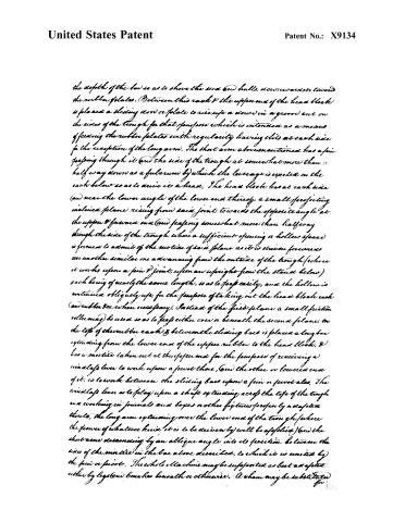
Page 4.
United States Patent
Patent No.: X9134
the depth of the box so as to shove the seed and hulls, downwards or towards the rubber plates. Between this rack & the upper end of the head block is placed a sliding bar or plate to rise up & down in a groove cut on the sides of the trough for that purpose which is intended as a means of feeding the rubber plates with regularity having slits at each side for the reception of the long arm. The short arm above mentioned has a pin passing through it & the side of the trough at somewhat more than half way down as a fulcrum by which the leverage is exerted on the rack below so as to drive it a head. The head block has at each side (and near the lower angle of the lower end thereof) a small projecting inclined plane rising from said joint towards the opposite angle at the upper & forward end (and passing somewhat more than halfway through the side of the trough where a sufficient opening or hollow space is formed to admit of the motion of said plane as it is driven forwards or another similar one advancing from the outside of the trough (where it works upon a pin & joint, upon an upright from the stand below) each being of nearly the same length, so as to pass easily, and the hollow is continued obliquely up, for the purpose of taking out the head block each (and rubber box when necessary). Instead of the first plane a small friction roller may be used so as to pass either over or beneath the second plane, on the top of the rubber rack & between the sliding bars is placed a long bar extending from the lower end of the upper rubber to the head block, & has a mortise taken out at the upper end for the purpose of receiving a windlass lever to work upon a pivot there, (and the other or lower end of it, is to work between the sliding bars upon a pin or pivot also. The windlass lever is to play upon a shaft extending across the top of the trough and working in journals and boxes, another fixture properly a safety thrust, the long arm extending over the lower end of the trough (where the power of whatever kind it is to be driven by) will be applied) and the short arm descending by an oblique angle into its position between the sides of the mortise in the box above described, to which it is united by the pin or pivot. The whole machine may be supported as best as a plate either by legs (and) benches beneath or otherwise. A sham may be substituted for
Page 5.
United States Patent
Patent No.: X9134
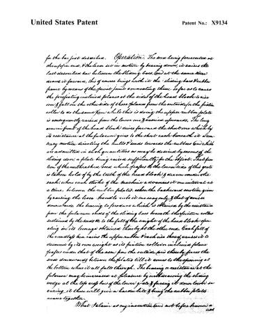
for the bar just described. Operation. The seed being presented at the upper end, & the lever set in motion by bearing down, it raises the last described bar between the sliding bars, & at the same time draws it forward, this of course brings with it the sliding bars & rubber frame by means of the pivot joints connecting them so far as to cause the projecting inclined planes at the sides of the head block to rise over & fall on the other side of those planes from the outside for the friction roller to do the same (and while this is doing) the upper rubber plate is consequently raised from the lower one & carried upwards. The long arm in front of the head block drives forward the short one which by its resistance at the fulcrum gives to the short rack beneath it a contrary motion directing the hulls & seeds towards the rubber & which are admitted in such quantities as may be desired by means of the sliding door, a plate being raised sufficiently for the object. That portion of the unthreshed seed which passes to the lower side of this gate is taken hold of by the teeth of the head block & drawn under the rack, where each stroke of the machine advances it one interval at a time, between the rubber plates, when the backward motion given by raising the lever handle rubs it one way only & that of course downwards, the bearing to produce which is obtained by the resistance from the fulcrum ends of the sliding bars beneath the friction rollers sustained by the seeds & to the fall of the weight of the head block operating on its leverage obtained thereby at the other end. Each fall of the windlass bar raises the upper rubber & each rise thereof causes it to descend by its own weight as its friction roller or inclined plane grasps under that of the arm from the outside & thereby forces the seed downwards between the plates till it comes to the opening at the bottom when it all falls through. The bearing or resistance at the fulcrum may be increased at pleasure by withdrawing the sliding wedge at the top end of the lower gate & forcing it down lower securing it there will give a harder bite & bring the rubber plates nearer together.
What I claim as my invention (and not before known) is
1101
Page 6.
United States Patent
Patent No.: X9134
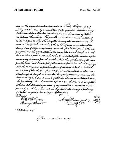
used in the above described Machine is, First, The principle of rubbing out the seed by a repetition of the operation directed always in the same line or by always rubbing one and the same way between two planes. Secondly, The peculiar structure or combination of the several parts viz). The use of the lower gates as constructed. The construction and combination of the rubber frame connecting of the sliding bars & strips composing the rack for the reception of the upper plate also the application of the head block with the friction rollers or inclined planes all attached thereto, and that of the inclined planes advancing inwards from the outside. Also the application of the arms from the said head block (end of the rack in front into which they play) (also the sliding door or plate in front of the head block to let in the hulls & seeds, also the lever (windlass) as constructed (and that construction of the trough as described being the provision for receiving the lower rubber plate (and so much of the Machinery as is claimed above. In testimony) that the above is a full clear and exact description of the construction and operation of my machine as invented or improved by me I have hereunto set my hand this twenty eighth day of August Eighteen hundred and thirty five
Witnesses
L. M. Wharton
Henry Stone
Moses Davenport
(2220 words)
(Patented October 6, 1835)
Published accounts: journal notice
Notice in the monthly list of patents, with remarks
Journal of the Franklin Institute, new ser., vol. 17 (1836), p. 327 · View the page
6. For a machine for Thrashing and Cleaning Clover, or Rice; Moses Davenport, Phillips, Somerset county, Maine, October 6.
Remarks. The machine here described consists of a long trough, containing the feeding, rubbing, and other apparatus. It is too complex for verbal description, but its characteristic feature appears to be, the passing of the seed between rubbing boards, covered with perforated metal, or otherwise made rough, the lower board being stationary, and the upper one, as it vibrates, bearing on the seed in one direction only, it being raised in the return stroke.
Published accounts: journal notice
Notice in the monthly list of patents (listed with a different spelling or date)
Journal of the Franklin Institute, new ser., vol. 17 (1836), p. 144 · View the page
Thrashing grain. -Moses Davenport, Phillips, Somerset County, Md.
Published accounts: journal notice
Notice in the monthly list of patents (listed with a different spelling or date)
Journal of the Franklin Institute, new ser., vol. 18 (1836), p. 43 · View the page
For a Thrashing machine; Moses Davenport, Phillips, Somerset county, Maine, December 28.
About this record
- Patentee
- the Journal of the Franklin Institute, Journal
- Date
- the Name and Date index of patents, USPTO records, Jim Shaw's X-patent list
- Invention
- the Name and Date index of patents
- Listed in
- the Name and Date index of patents, USPTO records, Jim Shaw's X-patent list, the Journal of the Franklin Institute, the Journal of the Franklin Institute, Journal, Burke's List of Patents (1847)
- The patentee's full name comes from the Franklin Institute's journal.
- Also listed in a contemporary journal or list under a different spelling or date; the record shown follows the standard lists.
- Burke's 1847 Patent Office list gives the same patent.