

Drawings and documents
National Archives restored drawings: drawing
John Bennock's Patent Drawing for a Steam Engine

National Archives, Restored Patent Drawings (Record Group 241) · Full-size scan at the National Archives · Catalog record
Show the text on the drawing Hide (38 words)
Words on the drawing as machine-read by the National Archives; not checked. Useful mainly for searching.
121. STEAM. / 1. ENGINES. / [150] Rotary. / 1850 / Rutary St-Enge / Concentrio-Piston. / sl. A, / CLASSEFICATION / 90684 / DIVISION / Them Engine / Patented 9th Sept 1835. / V.22.1.272. / Figs / Co / Fig6. / Fig / OB / Fig3
USPTO scan
The patent as scanned by the USPTO
-
 Page 1
-
 Page 2
-
 Page 3
-
 Page 4


U.S. Patent and Trademark Office · Google Patents
Show the transcription Hide (1,236 words)
Machine transcription (LightOnOCR) of the pages as scanned by the USPTO, most of them the handwritten copies made when the records were restored after the 1836 fire. Not checked; it can misread handwriting, so compare it with the scan.
Page 1.
9068X
J. Bennock,
Rotary Steam Engine.
Patented Sep. 9, 1835.
Fig. 1.
Fig. 2.
Fig. 3.
Fig. 4.
Fig. 5.
Fig. 6.
K. PETERS, PHOTO-LITHOGRAPHER, WASHINGTON, D. C.
Page 2.
John Bennock, Orono, Maine.
Letters Patent.
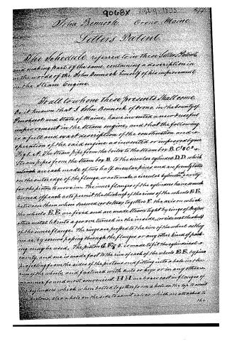
The Schedule, referred to in these Letters Patent, and making part of the same, containing a description in the words of the John Bennock himself of his improvement in the Steam Engine.
To all to whom these presents shall come,
Be it known that I John Bennock, of Orono, in the county of Penobscot and state of Maine, have invented a new and useful improvement in the steam engine, and that the following is a full and exact description of the construction and operation of the said engine as invented or improved by me.
Fig 1. A. The steam pipe from the boiler to the steam box B. C¹ & C². Steam pipes from the steam box B. to the circular cylinders D, D, which are each made of two half circular pieces and are firmly bolted on the outer edge of the flange, so as to make a circular cylindrical cavity for the piston to move in. The inner flanges of the cylinders have a much turned off each as to permit the thickness of the rims of the wheels E, E, between them when screwed (or bolted) together F. The axis on which the wheels E, E, are fixed and are made steam tight by rings of brass or other metal let into a groove turned in the inside, (or side next the wheel) of the inner flange. The rings are pressed to the rim of the wheel as they wear, by screws passing through the flanges or any other kind of packing may be used. The piston G. Fig 5. is made to fit the cylindrical cavity, and one is made fast to the rim of each of the wheels E, E, by pieces projecting from the sides of the pistons and fitting into a hole in the rim of the wheels, and fastened with nuts or keys or in any other manner found most convenient. H H are boxes cast in flanges of the cylinders which when bolted together form a hole on the top to admit the pistons. Also a hole on the side to admit valves which are attached to the
Page 3.
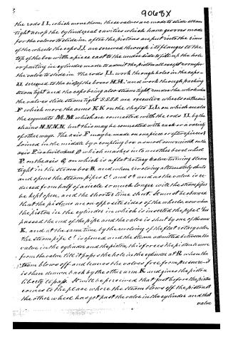
the rods I I, which move them. These valves are made to slide steam tight across the cylindrical cavities which have grooves made for the valves to slide in. After the pistons are put into the rims of the wheels the caps J J, are screwed through its flanges to the top of the box with a piece cast to the under side to fill up the hole or parting in cylinder made to admit the piston all except room for the valve to slide in. The rods I I, work through holes in the caps J J, screwed to the sides of the boxes H H, and work through packing steam tight and the caps being also steam tight, render the whole when the valves slide steam tight S S S S, are executive wheels on the axis F which move the arms K K on the shafts I I, on which are also the segments M M, which are connected with the rods I I, by the chains N N N N, but this may be connected with rack or a variety of other ways. The axis F may be made on one piece or of two pieces joined in the middle by a coupling box as most convenient. On the axis F is a bevel wheel O which meshes into another bevel wheel P, on the axis Q, on which is a flat rotary valve turning steam tight in the steam box B, and when revolving alternately shuts and opens the steam pipes C! and C? and as the valve is reduced from half of a circle so much longer will the steam pipes be kept open, and the shorter time shut. It must be observed that the pistons are on opposite sides of the wheels, now when the piston in the cylinder in which is inserted the pipe C has passed the end of the pipe and the valve is shut by one of the arms K, and at the same time by the revolving of the flat rotary valve, the steam pipe C! is opened and the steam admitted between the valve in the cylinder and the piston, this forces the piston to move from the valve till it passes the hole in the cylinder at R, when the steam blows off and leaves the valves free from pressure—it is then drawn back by the other arm K, and gives the piston liberty to pass. It will be perceived that just before the piston comes to the place where the steam blows off the piston at the other wheel has got past the valve in the cylinder and that
Page 4.
9068X 279.
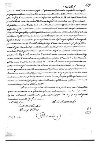
value is shut and the steam pipe C? opened which makes the piston in the cylinder perform the same operation and carries the other to the place where it was at first. Fig 2 is a section of one half of the cylinder D. H the box to admit the the piston C and the valve T. V. one half of the circular cavity in which the piston revolves B the hole when the steam blows off to which may be attached a pipe to carry the waste steam wherever required V shows the brass or other metal ring which by pressing or fitting to the sides of the rim of the wheel E Fig 4 renders it steam tight. W. the holes for the bolts to fasten the two half cylinders together. Fig 3. is a section of the cylinder D. at a right angle to fig 2. showing the semicircular cavity U with the brass ring V and the screws for pressing it forward. Fig 4. the wheel B with the section of the piston C showing the manner in which it is keyed to the rim of the wheel. Fig 5. a separate view of the piston C. Fig 6. the steam box B with the cover removed to show the revolving steam valve X and the ends of the steam pipes C¹ and C², also the end of the axis & of the bevel wheel P. That I claim as my invention and not previously known in the above described machine is, the using of two cylinders and the arrangement of the valves and pistons so as to produce a constant power, and also the rings of brass or other metal and the method of fitting them into the inner flanges of the cylinders, and the manner of pressing them to the sides of the rims of the wheels so as to render the cylinders steam tight.
In testimony that the above is a full and exact description of the construction and operation of my machine as invented or improved by me I have hereunto set my hand this fifteenth day of August eighteen hundred and thirty-five —
Witnesses
John Bennocks
C. A. M. Wharton
Henry Stone
(Drawing)
1240 wts
Ex.
Cox/11
Published accounts: journal notice
Notice in the monthly list of patents
Journal of the Franklin Institute, new ser., vol. 16 (1835), p. 358 · View the page
532. Steam engine.—John Bennock, Penobscot, Maine,
Published accounts: journal notice
Notice in the monthly list of patents (listed with a different spelling or date)
Journal of the Franklin Institute, new ser., vol. 17 (1836), p. 254 · View the page
For a Rotary Steam Engine; John Bennock, Orono, Penobscot county, Maine, September 0.
About this record
- Patentee
- Jim Shaw's X-patent list
- Date
- the Name and Date index of patents, USPTO records, Jim Shaw's X-patent list
- Invention
- the Name and Date index of patents
- Listed in
- the Name and Date index of patents, USPTO records, Jim Shaw's X-patent list, the Journal of the Franklin Institute, the Journal of the Franklin Institute, Journal, Burke's List of Patents (1847)
- The residence comes from the Franklin Institute's journal.
- Also listed in a contemporary journal or list under a different spelling or date; the record shown follows the standard lists.
- Burke's 1847 Patent Office list gives the same patent.