

Drawings and documents
National Archives restored drawings: drawing
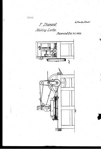
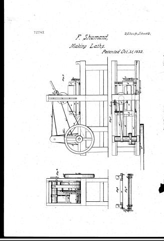
Francis Thumard's Patent Drawing for a Saw Mill for Cutting Laths

National Archives, Restored Patent Drawings (Record Group 241) · Full-size scan at the National Archives · Catalog record
Show the text on the drawing Hide (166 words)
Words on the drawing as machine-read by the National Archives; not checked. Useful mainly for searching.
144. WOOD WORKING / 3. SPECIAL WORK MACHINERY. / 2 Plate 1. / [174] Making Laths. / Trancis humard / JacoMitt for cutting Laths. / Vol ingsoq Partented betai./831 / ULASSIFIL ATION / 7274-x / SION / 1832 / J.y.2. / Tigl. / Sectern. / Front view. / References. a the log. b. B. headblooks e the carriage. d pitman e crank of large bandwhul. g horizontal Jawn h vertical eat law. 2 saroframe K zach and pinions / l. lever. m m rollersof the locoer Jection of caniage C. n. upper sectionofe. astides. p piron shaft. q.q pinions 22 racks. I Ragwheel t palls. u feeding hand / D.V. trippers. w w.". w.w." bands. / Tig 1. Conjitudinal section of law Mill. Sy.2 Front view. Ty.3. Endriew. Jig Sideview. / Sizes Top view. Its 6 Tection ofn the ofn upper part of the carriage. Orig. Sectional of the carriage / Patint offise Dee.g. 1841 / made under the direction of the Commissioner / of Patent in conformity with act af32 march 185% / fact. / 1/2 / Commessioner of Patent.
USPTO scan
The patent as scanned by the USPTO
-
 Page 1
-
 Page 2
-
 Page 3
-
 Page 4


U.S. Patent and Trademark Office · Google Patents
Show the transcription Hide (645 words)
Machine transcription (LightOnOCR) of the pages as scanned by the USPTO, most of them the handwritten copies made when the records were restored after the 1836 fire. Not checked; it can misread handwriting, so compare it with the scan.
Page 1.
7274X
F. Shumard,
Making Laths.
Patented Oct. 31, 1832.
2 Sheets, Sheet 1
Fig. 2
Fig. 1
Page 2.
7274X
F. Shumard,
Making Laths.
Patented Oct. 31, 1832.
2 Sheets: Sheet 2.
Page 3.
7274x Oct 31, 1892 509
Francis Shumard of Cincinnati Ohio
Letters Patent.
The Schedule referred to in these Letters Patent and making part of the same containing a description in the words of the said Francis Shumard himself of his Improvement in the Saw mill by which Laths &c cut with circular Saws.
To all whom it may concern, Be it known that I Francis Shumard of Cincinnati in the County of Hamilton and State of Ohio have invented an improvement in the saw mill, by the application of which circular saws are made to cut laths or other light work on the edge and the saw at one operation and that the following is a full and exact description of the said machinery as invented by me.
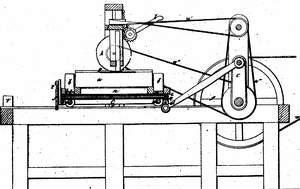
The log to be sawed into Laths or other strips is first cut to the required length, and then fixed upon a saw carriage with suitable head Blocks. This carriage may be made to traverse back and forward by means of any appropriate gearing, that which I commonly use, and which I prefer to any other, is the crank motion communicated from a revolving shaft by means of a pitman. The two shafts of the circular saws are in a frame which is made to slide up and down between vertical blocks above the log by means of a lever or rack and pinion or other contrivance. The frame may be raised or lowered so as to adapt the saws to the dimensions of the log. I usually employ one saw running horizontally and two or more running vertically which laths cut the laths or other strips to a proper thickness, whilst the former cuts them off at their ends.
The saws are made to cut as the log passes in either direction thereby saving the time which would otherwise be expended in drawing the log back. For the purpose of setting or of moving the log sideways the carriage is divided into two parts, one of which runs upon suitable rails on the other. An iron shaft under the upper section of the carriage has a pinion upon one of its ends which gears with a rack fixed on the lower side. I say a rack on the lower side of the shaft provided with pins and notched... only a fixed hand on the end of any shaft the log sideways to such a distance as shall correspond
Page 4.
7274x Oct 31, 1832
with the thickness of the logs to be cut. At each end of the frame on which the carriage moves, there are attached blocks or levers against which at any semi-revolution of the cranks, the hands strike and are lifted so as to act upon the saw wheel in the respective degree. By means of the drawings deposited in the Patent Office and there annexed thereto annexed, the various parts which I have described & their mode of action will be readily understood.
What I claim as my invention and for which I ask a patent is the causing the saw to cut as the log traverses in either direction, the mode of moving the log side ways as above described, the combined use of the vertical and horizontal saws, cutting the sides and edges of the laths simultaneously, the mode of adjusting the saws by means of the sliding frame and the general construction and arrangement of the apparatus by which the intended effect is produced.
Sgd. Witness
Issac Ripley
C. O. Williams
Francis Shumard
552½
Published accounts: journal notice
Notice in the monthly list of patents, with remarks
Journal of the Franklin Institute, new ser., vol. 11 (1833), p. 304 · View the page
The machinery used is described in very general terms, leaving, in its application, much to be reinvented by any one who should undertake to construct it from the specification and drawing deposited in the patent office. It appears, however, that there are to be two wedgelike pieces, the heads of which are segments of cylinders, and between these curved ends, the forging, or swageing is to be effected; there is to be a strong iron frame, within which these two pieces, which are called folding arms, are to be hung upon pins at their thinner ends. Upon the curved heads swages are to be placed, having the form adapted to the axe, or other article to be forged. These wedges, or segments, are made to vibrate by means of a crank and pitman, and, according to the drawing, they are to be forced up against each other by a kind * In the list of patents in the last number, the following was omitted:48. For an improvement in the mode of Cutting Laths by means of Circular Saws; Francis Shumard, Cincinnati, Hamilton county, Ohio, October 31.
Remarks. The specification of this patent will be found in the present number. American Patents for November, with Remarks. of windlass, thus following the metal as it enters the dies. The claim is to " the application of power, giving to the metal a squeeze or pressure in one direction only."
Published accounts: journal notice
Notice in the monthly list of patents, with remarks
Journal of the Franklin Institute, new ser., vol. 11 (1833), p. 319 · View the page
(The specification will appear in the next number.) SPECIFICATIONS OF AMERICAN Patents. Specification of a patent for an improvement in the Saw Mill, by the application of which circular saws are made to cut laths, or other light work, on the edge, and on the side, at one operation. Granted to. FRANCIS SHUMARD, Cincinnati, Ohio, October 31, 1832.
Remarks. The log to be sawed into laths, or other strips, is first cut to the required length, and then fixed upon a saw carriage, with suitable head blocks. This carriage may be made to traverse backward and forward by any appropriate gearing; that which I commonly use, and which I prefer to any other, is the crank motion communicated from a revolving shaft by means of a pitman. The two shafts of the circular saws run in a frame which is made to slide up and down between vertical cheeks above the log. By means of a lever, a rack and pinion, or other contrivance, the frame may be raised or lowered so as to adapt the saws to the dimensions of the log. I usually employ one saw running horizontally, and two, or more, running vertically, which latter cuts the laths, or other strips, to a proper thickness, whilst the former cuts them off at their edges. The saws are made to cut as the log passes in either direction, thereby saving the time which would otherwise be expended in drawing the log back. For the purpose of setting, or of moving, the log sideways, the carriage is divided into two parts, one of which runs upon suitable rails on the other. An iron shaft under the upper section of the carriage, has a pinion upon each of its ends, which operate upon racks on its lower side. A rag wheel on the head of the shaft, provided with palls, and acted on by a feed hand in the usual way, shifts the log sideways, to such a distance as shall correspond with the thickness of the laths to be cut. At each end of the frame on which the carriage moves, there are attached blocks, or trippers, against which, at every semirevolution of the crank, the hands strike, and are lifted so as to act upon the rag wheel in the requisite degree. EASTMAN'S Water Wheel. By means of the drawing deposited in the patent office, and the references thereto annexed, the various parts which I have described, and their mode of action, will be readily understood. What I claim as my own invention, and for which I ask a patent, is the causing of the saws to cut as the log traverses in either direction; the mode of moving the log sideways, as above described; the combined use of vertical and horizontal saws, cutting the sides and edges of the lath simultaneously; the mode of adjusting the saws by means of the sliding frame; and the general construction and arrangement of the apparatus by which the intended effect is produced. FRANCIS SHUMARD. Specification of a patent for an improvement in the Reacting Water Wheel. Granted to ROBERT EASTMAN, Concord, Merrimack county, New Hampshire, March, 1833. WITH TWO COPPERPLATES. To all whom it may concern, be it known, that I, Robert Eastman, of Concord, in the county of Merrimack, and state of New Hampshire, have invented certain improvements in the construction of the reacting water wheel, used for the driving of machinery by the reaction of water, by which improvements its action is rendered more perfect, and it is rendered self-regulating by the addition of a regulator, or governor; it is also made peculiarly compact, whilst it still affords sufficient inlet and outlet for the water to operate in the most effectual manner. And I do hereby declare, that the following is a full and exact description of my said improvements, reference being had to the drawings which accompany, and make part of, this specification. The wheel may be made in whole, or in part, of cast iron, or other materials may be employed in its construction. It may be cast in pieces like those represented in the drawings, or the form may be variously modified, whilst the same principles are retained. Its dimensions may also be changed, and when of a very small size, the number of floats may be reduced to fewer than eight, which is the number I generally employ, as shown in the drawings. A is the shaft of the wheel, terminating below at the step on the bridge-tree O, which is capable of being raised or lowered by means of a suitable rod, or rods, as shown at S. When eight floats are used, four of them are stationary, and four are moveable, and it is by means of the latter that the quantity of water to be expended is regulated. D represents the top rim of the wheel, which has a projecting fillet, d, cast on it, which is made to fit exactly in the opening of the cistern piece or plate, C. A similar rim is made for the under side of the wheel, but, on this, I usually place the fillet on the outer edge. These rims are to be attached to the stationary floats by means of screws, EASTMAN'S Water Wheel. or rivets. On the flooring piece C, the stationary floats, which may be cast in one piece with it, are shown by black lines, whilst the dotted lines represent the moveable floats, alternating with the former, and by their motion enlarging or diminishing the aperture at each of their ends. They are supported by bolts passing through them edgewise, and through the upper and lower rims. The plate F, having upon it the jointed arms, or connecting rods a, a, a, a, is intended to act on the moveable floats, in doing which it receives its motion from a regulator, or governor, to be presently described. A side and edge view of one of the moveable floats is given at E E, with the slot which admits of its being drawn by the connecting rods nearer to the shaft A. CC are cistern plates, which rest upon ledges c, C, c, c. These ledges are also shown in the section R. Bisa centrepiece, which I employ to connect the wheel to the shaft. TT are the bolts which connect and support the cistern pieces. The regulator, or governor, acts upon the same principle with those used for steam engines and other machinery, and is only so modified as to adapt it to the purpose to which I apply it. U U are the centrifugal balls, the jointed arms, N, of which act upon the sliding collar L. There are two wheels, MM, which I call the upper and lower blank wheels. In the upper blank wheel the collar L turns freely, whilst it is so connected with it by means of a ring and set screw, as to cause the two to raise and lower together. The two blank wheels are connected by the two bolts n n, and two pins rising from the plank V, and passing through the ears e e, serve to guide them steadily. The axis of the vertical blank wheel P, passes through the shaft A, and has, on each side of the shaft, an endless screw, K. These endless screws take into wheels H H, placed upon the rods I I, for the purpose of causing them to revolve. When the centrifugal force is much increased, the regulator will bring the lower wheel, M, into contact with P, and when sufficiently decreased, will bring the upper wheel, M, in contact with it, when the wheels H will be turned, and the pinions J J, on the lower ends of the rods I I, taking into the teeth in the openings in the plate F, and causing it to turn, will open or close the moveable floats. At a medium speed, neither of the wheels MM will be in contact with P. The regulator may, if preferred, be detached from the shaft, and carried by a band or otherwise, and be geared so as to operate on the rods I I; it may also be dispensed with entirely, and the wheel P, or some appendage operating in the same way, may be turned by hand, so as to set the floats in any required position. The cistern pieces CC, I prefer to make of wood, as they produce less friction than iron, when accidentally brought into too close contact with the wheel; and they are also, when worn, more readily and economically adjusted than if made of metal. As the water is admitted both above and below the wheel, its pressure is equalised, so that the weight of the column is not felt on the step. The two orifices likewise tend to give a full and equable supply of water to the wheel. What I claim as my invention, and for which I ask a patent, is the making the floats of a reaction wheel adjustible, as herein described. Vo. XI. No. 5.-MAY, 1833. 41 DAVIS' Gold Washing Machine. I also claim the application of the regulator or governor, to render them self adjusting. Likewise the manner of adjusting them by hand, enabling the operator to do so without the necessity of descending to the wheel, or in any way disturbing the arrangement of the apparatus. In effecting these objects, I do not intend to confine myself to the precise mode which is herein set forth, but to adopt any other which operates upon the same principle, and produces a similar result. ROBERT EASTMAN.
Published accounts: specification
Specification printed in the Journal of the Franklin Institute
Journal of the Franklin Institute, new ser., vol. 11 (1833), p. 319 · View the page
Text of the specification as printed in the Journal, from OCR; not proofread.
Specification of a patent for an improvement in the Saw Mill, by the application of which circular saws are made to cut laths, or other light work, on the edge, and on the side, at one operation. Granted to. FRANCIS SHUMARD, Cincinnati, Ohio, October 31, 1832. The log to be sawed into laths, or other strips, is first cut to the required length, and then fixed upon a saw carriage, with suitable head blocks. This carriage may be made to traverse backward and forward by any appropriate gearing; that which I commonly use, and which I prefer to any other, is the crank motion communicated from a revolving shaft by means of a pitman. The two shafts of the circular saws run in a frame which is made to slide up and down between vertical cheeks above the log. By means of a lever, a rack and pinion, or other contrivance, the frame may be raised or lowered so as to adapt the saws to the dimensions of the log. I usually employ one saw running horizontally, and two, or more, running vertically, which latter cuts the laths, or other strips, to a proper thickness, whilst the former cuts them off at their edges. The saws are made to cut as the log passes in either direction, thereby saving the time which would otherwise be expended in drawing the log back. For the purpose of setting, or of moving, the log sideways, the carriage is divided into two parts, one of which runs upon suitable rails on the other. An iron shaft under the upper section of the carriage, has a pinion upon each of its ends, which operate upon racks on its lower side. A rag wheel on the head of the shaft, provided with palls, and acted on by a feed hand in the usual way, shifts the log sideways, to such a distance as shall correspond with the thickness of the laths to be cut. At each end of the frame on which the carriage moves, there are attached blocks, or trippers, against which, at every semirevolution of the crank, the hands strike, and are lifted so as to act upon the rag wheel in the requisite degree. EASTMAN'S Water Wheel. By means of the drawing deposited in the patent office, and the references thereto annexed, the various parts which I have described, and their mode of action, will be readily understood. What I claim as my own invention, and for which I ask a patent, is the causing of the saws to cut as the log traverses in either direction; the mode of moving the log sideways, as above described; the combined use of vertical and horizontal saws, cutting the sides and edges of the lath simultaneously; the mode of adjusting the saws by means of the sliding frame; and the general construction and arrangement of the apparatus by which the intended effect is produced. FRANCIS SHUMARD.
DATAMP: illustration
Illustrations from DATAMP

DATAMP (Directory of American Tool and Machinery Patents), via the Internet Archive · Archived DATAMP page
About this record
- Patentee
- DATAMP
- Date
- the Name and Date index of patents, DATAMP, USPTO records
- Invention
- DATAMP
- Listed in
- the Name and Date index of patents, DATAMP, USPTO records, Jim Shaw's X-patent list, the Journal of the Franklin Institute, Burke's List of Patents (1847), the Journal of the Franklin Institute, Journal
- Burke's 1847 Patent Office list gives the same patent.