

Drawings and documents
National Archives restored drawings: drawing
Alanson Holmes' Patent Drawing for a Carding and Spinning (Machine)

National Archives, Restored Patent Drawings (Record Group 241) · Full-size scan at the National Archives · Catalog record
Show the text on the drawing Hide (355 words)
Words on the drawing as machine-read by the National Archives; not checked. Useful mainly for searching.
ALANSON P.OLMES. / 19. CARDING. / 450 / [28] Carding. / CARDING & SPINNING / Patented Jan 1810. VOL: 2. page 421. / CLASSIFIC / 1191 X / DIVISION / Side view / h,h, rollers with deep grooves / jif, rollers wound with wire / two posts / l, oval nat y chain. / two posts / side railing, / q,q, pulleys / 2,2, springs / D.D. two girls / D'. a third girt / zb / 3,3, statues / B' / main cylinder / 4,4,4,4,4, dividing rollers. / undards of main cylinder / 5,5, traversing rollers, wound with wite / Ge / 6, box with grooves in the sides / 30 / ii.vc. moving screws & standards / 7, cross pieces / n rollers. / 8,8, pulleys, / pers / 9,9, two cast iron coo wheels. / clearer / 10, 10, pinions, / A, bar fastened to the two under cross pieces / !ing boxes / B, spur wheel / 10, feeders / ,, rollers for rotting cloth / 6, penion with two teeth / VL, rolling cloth / D,VE, pulleys / dije, feeder pinions / F,F,F,F, it's drawing rollers / V pinion of 10 cogs on end of main shaft / G,G,vc: cast iron cog wheels of aifferent sizes / P, wheel of 00 cogs / Top view. / H, drum under the frame / 4, iron strap / x,x, Q.Cs pulleys on shanks of junions / r, pulley for moving chain rollers 1,1,1, / short woodeh rollers, fluted S covered with leather / pulley on gallows wheel shaft / L,L,L,L,L, iron levers / t, shank cog pulley / T' / R.T, shank cog & wheel / M,M, bars of iron / B' / N, the fliers y spindles. / и,и,и,и, pulleys / P. heart wheel / v, crank shuft pulley / R, pulley on the heart wheel shaft / W, leather strap, / S, pulley on the under feeder shaft / X,X, the doffers. / I, , long levers with a cross piece under the luart / 1, second doffer pulley / U, the gate / W,W, bars across the gate / Z, doffer pulleys so strap / standard for the first doffer / the crank. / C,C,C,C, Jour statues for holding the combs. / d,d, the combs / 60, screws nuts, / Patent Office / stalves projecting back to the arches / August 28 1845 / m.g.g, scc: strips of cards / palley on main Cylinder / made under the direction of the Commigroms of / Patents in Conformity with the act of 3:4 march / 1837 / Eamun Purke
USPTO scan
The patent as scanned by the USPTO
-
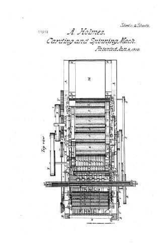 Page 1
-
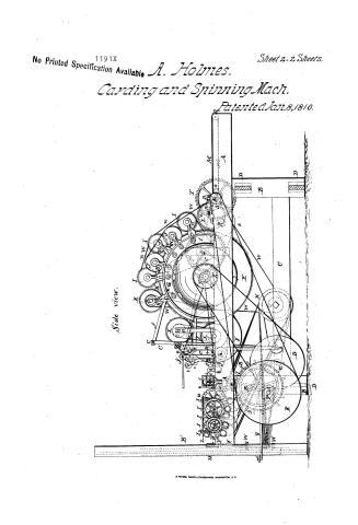 Page 2
-
 Page 3
-
 Page 4
-
 Page 5
-
 Page 6
-
 Page 7


U.S. Patent and Trademark Office · Google Patents
Show the transcription Hide (2,207 words)
Machine transcription (LightOnOCR) of the pages as scanned by the USPTO, most of them the handwritten copies made when the records were restored after the 1836 fire. Not checked; it can misread handwriting, so compare it with the scan.
Page 1.
1191X
A. Holmes.
Carding and Spinning Mach.
Patented Jan. 8, 1810.
Sheet 1-2 Sheets.
Top view
M. PETERS, PHOTO-LITHOGRAPHER, WASHINGTON, D. C.
Page 2.
1191X
No Printed Specification Available
A. Holmes.
Carding and Spinning Mach.
Patented Jan. 8, 1810.
Sheet 2 - 2 Sheets.
Side view.
Page 3.
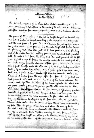
Jan 8 1810
Alanson Holmes
Letter Patent
The schedule referred to in these Letters Patent, making part of the same, containing a description in the words of the said Alanson Holmes himself of his machine for carding & spinning wool by one continued operation.
The frame of the machine is 10½ feet in length, 3½ feet in breadth and two feet 10 inches in height, consisting of two cap pieces, two posts framed into the cap piece 2 ft. from the end intended for feeding, 2 ft. 3 inches long. Two similar posts framed into the caps 5½ ft. still further toward the finishing end. Two other posts 6½ ft. long framed on to the finishing end of the caps. Two side railing framed into the short posts parallel with the caps 1 foot from the lower end. Two girts framed into the first pair of posts across the frame one directly under the side railing; the other one inch down from the shoulder; a third girt is framed into the second pair of posts directly under the other end of the railings. Timber, caps & short posts 7 by 4 inches, side railing 3 by 6 inches, girts 4 by 6 inches, long posts 3 by 4 inches, main cylinder 2 ft 10 inches diameter raised on standards 3 inches from the caps, 4 five feet from the feeder end, an arch framed into each cap at the ends of the main cylinder, the circle 1 inch less than the circle of the main cylinder; in which arches are fixed moving screws & standards for the other cylinders, viz: three chain rollers, two strippers & fancy. The fore cleaner a cylinder of 9 inches diameter is placed on the caps, hung on sliding boxes taken from the feeder & delivers it to the main cylinder. The first chain roller is next hung on the arches, is stripped by the fore cleaner. Then the first stripper & second chain roller. Then the second stripper & third chain roller working by pairs. Then the fancy, which raises and clears the wool of knots. The chain rollers 6½ inches in diameter. The strippers 3 inches, the feeders are 17½ in. diameter & roll together, drawing the wool from a rooling cloth of 2½ ft. in length on rollers of 2 in. diameter driven by a pinion on one end of the lower. On the same end there is a pinion on the
Page 4.
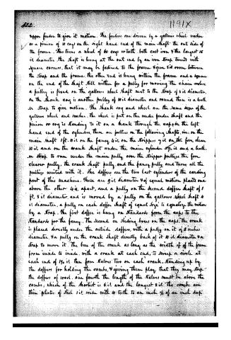
upper feeder to give it motion. The feeders are driven by a gallows wheel washer or a pinion of 10 cogs on the right hand end of the main shaft the out side of the frame. This turns a wheel of 60 cogs or teeth, both cast iron & the largest is 12 diameter. The shaft is hung at the out end by an iron strap turned with square corners, that it may be fastened to the frame & give 8" room between the strap and the frame. The other end is hung within the frame and a square on the end of the shaft still within for a pully for moving the chain rollers. A pully is fixed on the gallows wheel shaft next to the strap of 5 1/2 diameter. On the shank cog is another pully of 10 1/2 diameter and round there is a leath. or strap to give motion. The shank cog and wheel are the same name of the gallows wheel and washer. The wheel is put on the under feeder shaft and the pinion or cog is standing to it on a shank through the caps on the left hand end of the cylinders. There are pulleys on the following shafts, viz: on the main shaft 1 ft. 11 1/2 in on the fancy 4 1/2 in on the strippers 7 1/2 in on the fore clean 10 1/2 in and on the crank shaft under the main cylinder 8 1/2 in and a leath. or strap to run under the main pully over the stripper pulleys. The fore cleaner pully, the crank shaft pully, and the fancy pully and turns all the pulleys united with it. The doffers are the two last cylinders of the carding part of this machine. These are 9 1/2 diameter & of equal motion placed one above the other 4 1/2 in. apart, and a pully on the second doffer shaft of 1 ft. 5 1/2 diameter, and is moved by a pully on the gallows wheel shaft 4 1/2 diameter, a pully on each doffer shaft of equal size to equalize the motion by a strap. The first doffer is hung on standards from the caps to the standards for the fancy. The second on sliding boxes on the caps. The crank is placed directly under the outside doffers, with a pully on it of 5 inches diameter, & a pully on the crank shaft directly back of it 10 1/2 diameter & a strap to move it. The box of the crank as long as the width of of the frame from inside to inside, with a crank at each end, to sweep a circle at each end of 1 1/2 in. then four stalers two on each crank, standing up by the doffers for holding the combs, & giving them play that they may strip the doffers of wool. One fourth the length of the stalers must be above the combs, which of the shortest is 6 1/2 in and the longest 8 1/2 in. The combs are thin plates of steel 1 1/2 in wide with 10 teeth to an inch 1/2 of an inch deep.
Page 5.
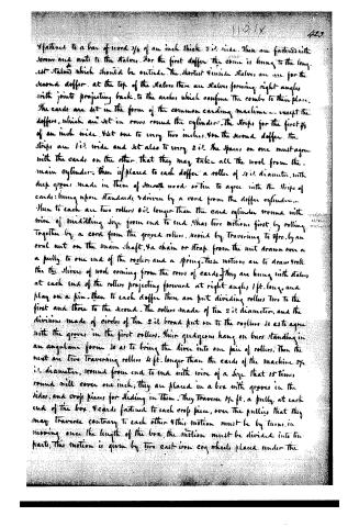
fastened to a bar of wood 3/4 of an inch thick 2' wide. These are fastened with screws and nuts to the staves. For the first doffer the course is hung to the longest stave which should be outside. The shortest inside staves are used for the second doffer. At the top of the staves there are staves forming right angles with joints projecting back to the arches which confine the course to their place. The cards are set in the form of the common carding machine—except the doffer, which are set in rows round the cylinder. The strips for the first 3/4 of an inch wide. Set one to every two inches. For the second doffer the strips are 1' wide and set also to every 2'. The spaces on one must agree with the cards on the other, that they may take all the wool from the main cylinder. Then is placed to each doffer a roller of 1/2" diameter, with deep grooves made in them of smooth wood or tin to agree with the strips of cards; hung upon standards, and driven by a cord from the doffer cylinder. Then to each are two rollers 6' longer than the card cylinder round with wire of middling size from end to end. Has two motions, first by rolling together by a cord from the grooved rollers, second by traversing to 4' by an oval nut on the main shaft, a chain or strap from the nut drawn over a pulley to one end of the rollers and a spring. These motions are to draw roll the the slivers of wool coming from the rows of cards. They are hung with staves at each end of the rollers projecting forward at right angles 1 ft. long, and play on a pin. Then to each doffer there are put dividing rollers two to the first and three to the second. The rollers made of tin 2" diameter, and the divisions made of circles of tin 2" broad put on to the rollers so as to agree with the grooves in the first rollers. Their guides hang on bars standing in an angular form so as to bring the slivers into one pair of rollers. Then the next are two traversing rollers 4 ft. longer than the cards of the machine 2 3/4" diameter, round from end to end with wire of a size that 15 turns round will cover one inch; they are placed in a box with grooves in the sides, and cross pieces for sliding in them. They traverse 1 1/2 ft. a pulley at each end of the box. 4 cards fastened to each cross piece, over the pulleys that they may traverse contrary to each other. This motion must be by turns, in moving over the length of the box, the motion must be divided into ten parts; this motion is given by two cast-iron cog wheels placed under the
Page 6.
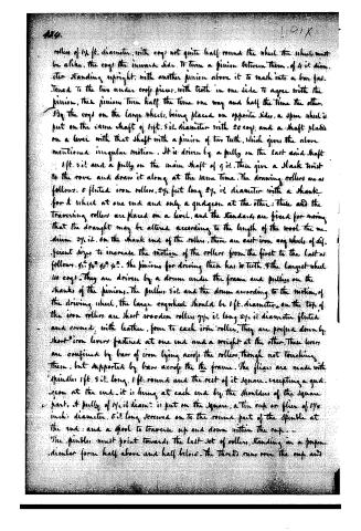
rollers of 1½ ft. diameter, with cogs not quite half round the wheel, the wheel must be alike, the cogs the inward side, to turn a pinion between them, of 4 in diameter standing upright, with another pinion above it to mesh into a bar fastened to the two under cogs pieces, with teeth in one side to agree with the pinion, then pinion turn half the time one way and half the time the other. By the cogs on the large wheels, being placed on opposite sides, a spur wheel is put on the same shaft of 1 ft. 5 in. diameter with 20 cogs and a shaft placed on a level with that shaft with a pinion of two teeth, which gives the above mentioned irregular motion. It is driven by a pully on the last said shaft 1 ft. 5 in. and a pully on the main shaft of 9 in. These give a slack twist to the rope and draw it along at the same time. The drawing rollers are as follows: 5 fluted iron rollers, 2½ feet long 2½ in. diameter with a shank for a wheel at one end and only a quidgeon at the other: These and the traversing rollers are placed on a level, and the standards are fixed for moving that the draught may be altered according to the length of the wool the medium 3½ in. on the shank end of the rollers, there are cast-iron cog wheels of different sizes to increase the motion of the rollers from the first to the last as follows: 4½, 4, 4, 4, 4. The pinions for driving them has 10 teeth, & the largest wheel 40 cogs. They are driven by a drum under the frame and pulleys on the shanks of the pinions. The pulleys 5 in. and the drum according to the motion of the driving wheel, the large cogwheel should be 1 ft. diameter. On the top of the iron rollers are short wooden rollers 9½ in. long 2½ in. diameter fluted and covered with leather, four to each iron roller. They are pressed down by short iron levers fastened at one end and a weight at the other. These levers are confined by bars of iron lying across the rollers, though not touching them, but supported by bars across the frame. The flairs are made with spindles 1 ft. 5 in. long, 1 ft. round and the rest of it square, excepting a quidgeon at the end. It is hung at each end by the shoulders of the square part, & pully of 1½ in. diam. is put on the square, a tin cup or flue of 1¾ inch diameter, 5 in. long screwed on to the round part of the spindle at the end: and a spool to traverse up and down within the cup. The spindles must point towards the last set of rollers, standing in a perpendicular form half above and half below. The thread runs over the cup and
Page 7.
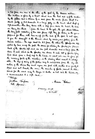
is led from one end to the other of the spool by the traverse motion. This motion is given by a heart wheel near the back end of the machine by the feeder and is driven by a cord from the under feeder shaft & a small pully of 4 in diameter to a large pully on the heart wheel shaft of 2 ft. diameter, then long levers with a crook piece under the heart. The levers are hung two thirds from the heart to the gate. The gate stands between the long posts consisting of two side pieces 5 ft. long for sliding in the grooves prepared for them, with bars across for the ends of the spools to rest upon to give the draught to the thread and by rising and falling gives the traverse motion. The crook must be 6 in from the rollers. The spindles are supported by bars across the posts. The drums for driving the spindles are placed back of the spindles 3 ft. and are one foot diameter and a band from the drum to each wheel on the spindles. One drum to each set of spindles, tying level which gives a half crook to the bands. No exact rule can be given for the moving parts of the machine, as the driving wheel cannot be always alike. The size of many of the pulleys may be calculated from the size and motion of the drums they must agree one part with another so as quickly to draw and not break the rove. The number of spindles cannot be determined for the card may be longer or shorter as best suits the builder. 24 is recommended to a 2 ft. card.
Wiltshire
Jonathan Brigham
with Spinnar.
Alanson Holmes
Drawing Made
A. L. H.
Card
1196.
About this record
- Patentee
- DATAMP
- Date
- the Name and Date index of patents, DATAMP, USPTO records
- Invention
- DATAMP
- Listed in
- the Name and Date index of patents, DATAMP, USPTO records, Jim Shaw's X-patent list, S. A. Elliot's printed list of patents, Burke's List of Patents (1847)
- S. A. Elliot's printed list of patents gives the same name and date.
- Burke's 1847 Patent Office list gives the same patent.