

Drawings and documents
National Archives restored drawings: drawing
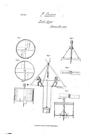
Pelig Easton's Patent Drawing for a Machine for Settling Wells in or Under Water

National Archives, Restored Patent Drawings (Record Group 241) · Full-size scan at the National Archives · Catalog record
Show the text on the drawing Hide (133 words)
Words on the drawing as machine-read by the National Archives; not checked. Useful mainly for searching.
Polay Easton / Patented Cr. / Machine for settling Willsin / Vol. 2. pg. 481. / CLASSIFICATION / or under Water / 1203 X / Pat'd. Feby. 15510 / Par. Fely, 1. 1810. / DIVISION / Ofig ju. / stigl. / And grey / in2. / Ayb. / Lig.8. / Lig.7. / Aigs. / References. / Jig. i. Bottom view of said Machine. / 2. / Indeview. view. / 4. / bection. / Ty.r. / butters Lideoiew / showing Topicew the hing. / make / machine / a. barrel. e.e id. d. d. braces / e. Topbrade. g socket. h. pintle / i.i.i.i. side cutters. / K. the socket pintle l. the cutters. m the hings. / Thigh / n. the traveller O.O. the braces. / Patent affice hard / Anad under in dinction of the Comm pioner of Catents / in conformity with act of I march 1837 / Mengh Elinworth / Correct / Commits ioner of Patents.
USPTO scan
The patent as scanned by the USPTO
-
 Page 1
-
 Page 2
-
 Page 3
-
 Page 4


U.S. Patent and Trademark Office · Google Patents
Show the transcription Hide (972 words)
Machine transcription (LightOnOCR) of the pages as scanned by the USPTO, most of them the handwritten copies made when the records were restored after the 1836 fire. Not checked; it can misread handwriting, so compare it with the scan.
Page 1.
1203X
P. Easton.
Earth Auger.
Patented Feb. 1, 1810.
Fig. 1.
Fig. 2.
Fig. 3.
Fig. 4.
Fig. 5.
Fig. 6.
Fig. 7.
Fig. 8.
THE GRAPHIC CO. PHOTO-LITH. 39 & 41 PARK PLACE, N.Y.
Page 2.
1203X Feb. 1, 1810 40
Riley Coston
Letters Patent.
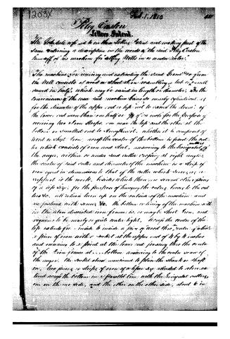
The Petitioner refers to his Letters Patent not making part of the same containing a description on the mode of the said Riley Coston himself of his machine for "sinking Wells in or under water."
The machine for receiving and extracting the sand Gravel &c from the Well consists of wood or sheet Iron resembling a tub or barrel, turned in half, which may be varied in length or diameter, for the convenience of the user said machine being so nearly cylindrical as for the diameter of the upper end or top not to exceed the diameter of the lower end more than one half or 3/4 of an inch for the purpose of receiving two Iron Sheeps, one near the top and the other at the bottom or smallest end to strengthen it, whether it be composed of wood or sheet Iron, near the center of the bottom is fixed the cutter which consists of iron and steel, answering to the horizontal of the auger, within or under said cutter cropping at right angles, the center of said cutter and diameter of the machine is a strip of iron equal in dimensions to that of the cutter which serves as a vertical to the works, besides which there are several other pieces of a like size, for the purpose of hanging the cutters, braces to the cutters &c. all which lie on the outside of the machine and are fastened with screws &c. the bottom or lining of the machine with the above described iron frame is, or may be sheet Iron, and requires to be nearly or quite water tight. Across the center of the top extends from inside to inside a piece of wood the center of which is a piece of iron with a socket at the upper end of it by 4 inches and running to a point at the lower end passing thru the center of the Iron frame at ... bottom answering to the center or axis of the auger, the socket above mentioned to place the shank or shaft in, two pieces or strips of iron of a like size attached to the ends and across the bottom in a parallel line with the horizontal cutters, one on the one side, and the other on the other side, about 6 in
Page 3.
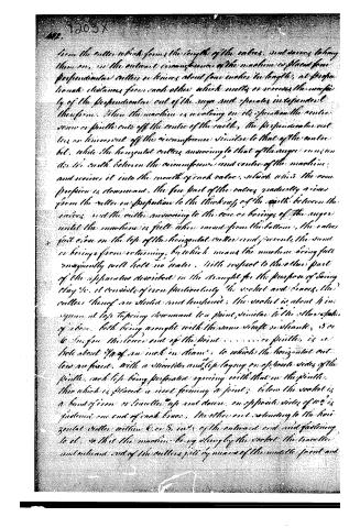
from the cutter which forms the trough of the valves, and does not lay them on, as the outward circumference of the machine is placed from perpendicular cutters or knives about four inches in length, at proportional distances from each other which melts or removes the sharpness of the perpendicular cut of the auger and operates independently therefrom. When the machine is revolving on its operation the centre screw or pinion cuts off the centre of the earth, the perpendicular cutters or knives cut off the circumference similar to that of the centre bit, while the horizontal cutters answering to that of the auger run under the earth between the circumference and centre of the machine, and receive it into the mouth of each valve, which when the compression is downward, the free part of the earth gradually rises from the cutter in proportion to the thickness of the earth between the valves, and the cutter answering to the core or bearings of the auger until the machine is full when raised from the bottom, the valves fast close on the top of the horizontal cutters and prevent the sand or bearings from returning, by which means the machine being full inequitably will hold no water. With respect to the other part of the apparatus described in the draught for the purpose of being clay &c. it consists of iron particularly the socket and braces, the cutters thereof are steel and tempered, the socket is about 4 inches square at top tapering downward to a point, similar to the other spokes of above, both being wrought with the same shaft or handle, 3 or 6 inches from the lower end of the point . . . . . . a pinion, is a hole about 3/4 of an inch in diameter, to which the horizontal cutters are fixed, with a shoulder and lip laying on opposite sides of the pinion, each lip being perforated agreeing with that in the pinion, there which is placed a screw forming a joint; below the socket is a band of iron or bristles up and down, on opposite sides of which is fastened one end of each brace, the other end extending to the horizontal cutter within 6 or 8 inches of the outward end and fastening to it, so that the machine being slung by the socket the braces and outward end of the cutters pass by means of the middle joint and
Page 4.
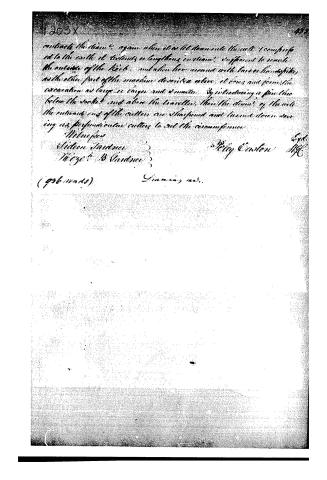
contracts the chain; again when it is let down into the well I am prepared to the earth it extends a lengthens instantly sufficient to reach the outsides of the Rock, and when here around with bars or handspikes as the other part of the machine described above, it does and performs the excavation as large as large and 4 minutes. By introducing a pin line below the socket and above the traveller, then the diameter of the well the outward ends of the cutter are sharpened and turned down serving as perpendicular cutters to cut the circumference.
Witnesses
William Gardner
George B. Gardner
Riley Carson
Expt. Mgr
(936 words)
Gunning, m.s.
About this record
- Patentee
- DATAMP
- Date
- the Name and Date index of patents, DATAMP, USPTO records
- Invention
- DATAMP
- Listed in
- the Name and Date index of patents, DATAMP, USPTO records, Jim Shaw's X-patent list, S. A. Elliot's printed list of patents, Burke's List of Patents (1847)
- S. A. Elliot's printed list of patents gives the same name and date.
- Burke's 1847 Patent Office list gives the same patent.