

Drawings and documents
National Archives restored drawings: drawing
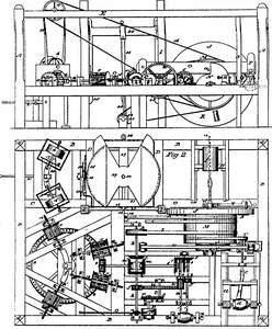
Mellen Battle's Patent Drawing for a American Wheel-right Labor Saving Machine


National Archives, Restored Patent Drawings (Record Group 241) · Full-size scan at the National Archives · Catalog record
Show the text on the drawing Hide (621 words)
Words on the drawing as machine-read by the National Archives; not checked. Useful mainly for searching.
Sheet 1. 144. WOOD, WORKING MACHINES. / MELLEN / BATTLE / Male 1 / #65 / Tenoning and Boring. / AMERICAN WHEEL-RIGHT LABOR SAVING MACHINE. / neierence / CLASSIFICATION / Patented April 4th 1810. / Vol 2 page. 486m / 12577 / AAA four corner posts DIVISION. / B.B.B. girls 2ftbin. from floor- / C, - cross girt, which lies lengthwise of frame / D,D, two girls. / E,E,E, four plates- / Fig.1 / Side view / P,- girt on top of frame / G, counter girt. / 25. / H, girl 10' long. / I,I, two fender posts / 37 / J, man upright wheel / 224 / K,K,K, three 2 1' 022 jonters in wheel. / iron shaft- / M, cylinder on shaft(L) of wheel (J) / N, / double scroll on Do / ml / a, pen 2.12 wooden shaft. O.- / 70 / P iron head which contains a socket for recuvinga double buzz(a) / de / R gain in iron head to recieve a cutter. / SS, two fonder posts between which works the shaft(0,). / T', cylinder- with iron spindle (b) sawbit (c) for tenonting / the spokes. / 21. / и carriage for directing the hub (d) & spoke (e) to the saw-hit(c). / 24 / V... crain carriage for dressing the spokes / 22. / W, socket in end of main shaft, to recure an auger for boring the / 23. / Centre of hub fjon carriage(g) / h, uron spindle with two bevel wheels (2,2,) opiniont) & & wooden / cylinder k) & strap mi,m, two uversing bevel whats / 28 / XXS / iron spindle for the purpose of turning the rim wheel. / n, two collars & iron hand (0) one end of which plays in a / transverse grooving(r) in the rinz of woodrn wheel (P) / q spindle in wheel (p)... r.wheel on spindle(q which is turned / 27. / by pinion (3) on end of spindle (t) which passes through / Figi2. / connecting wheel (u) which is turned by pinion (jon spindle(h) / w,... a long pinion which turns pinion (y) with spindle's bitt... / Top View, with the upperplates too / spindle with bitte(h) for bering the / 29. / (E.gc) removed. / ziz a hub 2.2. 2.2. four plummer blocks. / the / 30 / 1.34 / 3, iron plate with rach end forked, through which passes a / screw (4.) on spindle leading through bevel wheel 5. which / turns a counter Spindle (6.) with two bevel wherls (7.8.172.) / 32 / 8. horizontal face wheel 9 iron upright wheel which turns / 27 / face wheel( 10. iron spindle on which hangs bevel wheel / 26 / (m') which is turned by reversing whrels(2.2) / 25 / 2½ / 11, 11,11,11, four iron upright whreds / 22 / 12,12,12,12. four iron spindles with screws dt one and of ofeach and bitts(.z.z've / 36 / 13 collars for the screws to work 111 / at O the for boring a Follow(t) / 14 / shall top of frame with three cylinders (15,15,15.) / 16.16, which hang upon two iron spindles (17,17) with two / (18,18,) for sawing off a Follow With proper bevel / / block for raising the follow (19) to Her saws (18),.- by means / of lever (21.) 22. cylinder with crank(23.) & pitman (24.) leading / the saw-gate (25.) which hang two saws (26,26,) with teeth both / 9. / 10. / 6. / 3. / 10 / DA / ways / 27. square carriage up to the saws between / the saw-gate to any assigned distance, by meansola scrrw(28); / Patent Office / 29. ... reversing carriage on square carriage which turns upon / Oct 1846 / a contre(30.). The reversing carreage is moved forward and / backward by means of hand 31,) and dog(32) and two rag wherts / Made under the direction of the Commifsioner / 33,33..with teeth both ways 34...pinion for working a rack (35) on the / 8. / of Patents in conformity with act of 3rd of / reversing carriagel / March 1837 / strap leading from the main cylinder( M) to one of ther cylinders / 10 / on top of frame. for turning the two saws(18,18.) by straps (37.37.) - / Durke / 38 / 38 plummer blocks for holding the hub when is bored / S! / Lo / Commiprior Patents / August A. You Schmidt Del: / of
Sheet 2. ASSIFICATION / 144. WOOD WORKING MACHINES. / 1257 X / Tenoning and Boring. / DIV ISION. / the musuler / M. Barile / Shi21 / Pat, Apr. 4.1810 / # 1257 X / Fights. 3. / Top view of the upper part of frame / 0 O / 15 / 15 / 36 / mm / 15 / E' / D D
USPTO scan
The patent as scanned by the USPTO
-
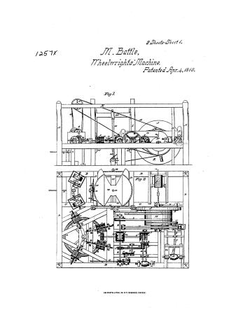 Page 1
-
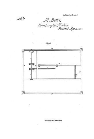 Page 2
-
 Page 3
-
 Page 4
-
 Page 5
-
 Page 6


U.S. Patent and Trademark Office · Google Patents
Show the transcription Hide (1,595 words)
Machine transcription (LightOnOCR) of the pages as scanned by the USPTO, most of them the handwritten copies made when the records were restored after the 1836 fire. Not checked; it can misread handwriting, so compare it with the scan.
Page 1.
1257X
2 Sheets-Sheet 1.
M. Battle,
Wheelwrights' Machine.
Patented Apr. 4, 1810.
Fig 1
Fig 2
A.M. PHOTO-LITHO. CO. N.Y. (OSBORNE'S PROCESS)
Page 2.
1257X
2 Sheets-Sheet 2.
M. Battle,
Wheelwrights' Machine.
Patented Apr. 4, 1810.
Fig 3

A.M. PHOTO-LITH. CO. N.Y. (DEBORNE PROCESS)
Page 3.
No. 77
1257X
Mellin Battle
April 4, 1810
Letters Patent (Patent No. 4, 1810)
The schedule referred to in these Letters patent and making part of the same, containing a description in the words of the said Mellin Battle himself of his American wheel rights Labor saving Machine
The frame of the Machine should be fourteen feet six inches long, & eleven feet wide and seven feet high, the frame will consist of four corner posts, seven inches square, four girts seven inches square, to lie horizontally in the frame, two feet six inches from the floor, one cross girt seven by six inches square, to lie lengthwise in the frame, four feet from one side, and two feet six inches from the floor, two girts seven by six inches square, to lie four feet six inches apart, and four feet six inches from one end, two feet six inches from the floor. Iron plates five by three inches square, for metal in to the head of the four corner posts seven feet from the floor, one girt five by three inches square, lying lengthwise in the frame seven feet from the floor, three feet six inches from one side, one counter girt seven feet long, five by three inches square, and four feet from one end in to which a girt is framed five by three inches square and ten feet long lying lengthwise in the frame, on which hang two fender posts six inches square which reach the floor; the Machinery will consist of one main upright wheel five feet in diameter four inches thick, in the rim of which will be placed three iron bars four inches from the circumference and the said bars are to be placed in the same manner as they are in a common plow wheel which hangs up on a shaft of iron one inch and a half square, three feet six inches long, near the end one end of the frame and on said shaft a wheel connected with the wheel a cylinder of one foot nine inches long and three feet in diameter, there is one wheel shaft to be rotated with said cylinder a double scroll to raise nine inches, one scroll plays one iron pin through a wooden shaft nine by three inches square seven feet long, on the end of said shaft and two feet six inches from the iron pin, will be fixed an iron head in the form of a hammer in the face and under side of which, will be a socket to receive a double bar.
Page 4.
two inches wide and an inch thick, and on the side of said iron head, will be a groove to receive the better three inches wide, said shaft will play up and down between the four parts, said iron head will play by the side of an upright piece with a groove in the side to receive a spoke, in such a manner that the better in the iron head will never said spoke, there will be parallel with the shaft of the main wheel a cylinder of wood through which passes an iron spindle in the end of which is a saw bit for the purpose of turning the other end of the spoke and bringing the hub, also a carriage to direct the hub and spoke to the saw bit, the said bit is turned by a strap passing over its cylinder one to the main cylinder, by the side of the face of the main wheel stands a brass carriage, with a groove suitable to receive spoke, hung in such manner that when the spoke is in the groove it will carry it to the face of the main wheel, in such a manner that the jointed iron in said wheel will drop it, likewise a socket in the end of the main shaft to receive an auger for boring the center of the hub, also a carriage that will carry the hub to the auger, and from said carriage to the end of the main shaft will run an iron spindle for the purpose of turning the rim of a wheel, there will be and iron spindle parallel with the main shaft four feet six inches long one inch and a half square, and on said spindle will be a wooden cylinder to receive a strap which leads to the main cylinder, likewise on said spindle will be two bevel wheels and one pinion, said wheels will stand with their bevels facing each other and at such distance as to receive between them two revolving bevel wheels, said wheels are to be at least iron, on the end of said spindle stands two collars, between which works an iron hand one end of which is made fast, the other end of said hand plays in a groove grooving in the rim of a wooden wheel, said wooden wheel hangs upon a
Page 5.
spindle parallel with the above said spindle, being one foot six inches long and one inch square, and on the end of said spindle hangs an iron wheel which is turned by a pinion upon the end of a spindle which passes through a large iron upright connecting wheel which wheel is turned by a pinion on the spindle containing the two bevel wheels, the motion of said wheel will be six times to the regulating wheel once, said connecting wheel works into a pinion of six inches long and four inches diameter, through said spindle layeth horizontal spindle, in the end of which is a bit, said pinion turns a pinion of four inches diameter and one inch thick, through which runs another horizontal spindle in the end of which is a bit, said spindle will lie in such a manner as to have the lines for motion in a line, on each end of said spindle, there will be a collar of six inches long and said collars work by four iron Plummer blocks, on each end of said blocks are screws and nuts, and on the end of said spindle on the opposite end of the bit is an iron plate with each end for key, through the center of the plate is a screw on a spindle leading through a bevel wheel which turns a conical spindle with two bevel wheels one of which plays in the reversing wheel, on horizontal face wheel four feet six inches in diameter, said wheel to be of wood or iron the top of said wheel to be two feet six inches from the floor; and the said wheel is turned by an upright wheel of iron, which hangs upon an iron spindle, and on the end of said spindle, hangs an iron bevel wheel which is turned by the reversing bevel wheel, said face wheel turns four iron upright wheels hung upon four iron spindles laying in such a manner, that with bits in the end of said spindle they will bore a Vello, in the opposite end of the spindles containing the four bits is a screw working in the Vello; all the collars contain screws and nuts so that they are moveable, all of said spindles containing bits are driven to any given distance by means of the screws and collars on the end of the spindles and return by the reversing
Page 6.
and regulating wheels, also two Plummer blocks that hold the bed when its bands, there is one shaft of seven feet hanging upon the top of the frame, on which is three cylinders, upon one cylinder is a strap leading to the cylinder of the main wheel, and from the other two cylinders runs two bands to two wheels, said wheels hung upon two iron spindles on the spindle is a collar to project out half an inch; between the collars hung two brass saws laying in such manner as to saw off both ends of a feller at any given length with their proper bevel. Said feller rests to the saws by means of a block on which it is just to rest which moves by means of a lever, a strap from the main cylinder leading over another cylinder on which is an iron crank affixed to which is a Pitman leading to the saw gate which hung upon the aforesaid fender posts, in said gate hangs two saws said saws contain teeth on both sides standing towards the fender posts, on the side of the saw gate is a square carriage which moves up the saw between the saw gate by means of a screw to any assigned distance, and on said carriage is a reversing carriage, which turns upon a center in the middle of the square carriage, the reversing carriage is moved backwards and forwards by means of a hand and dog and two Rag wheels with teeth both ways, on the shaft leading through the Rag wheels is a pinion working a Rack on the reversing carriage.
Witnesses:
John Bernard
Pharis Bernard
(1518 words) (Patented April 4, 1810.)
Drawing Made
Feb.
DATAMP: illustration
Illustrations from DATAMP

DATAMP (Directory of American Tool and Machinery Patents), via the Internet Archive · Archived DATAMP page
About this record
- Patentee
- DATAMP
- Date
- the Name and Date index of patents, DATAMP, USPTO records
- Invention
- DATAMP
- Listed in
- the Name and Date index of patents, DATAMP, USPTO records, Jim Shaw's X-patent list, S. A. Elliot's printed list of patents, Burke's List of Patents (1847)
- S. A. Elliot's printed list of patents gives the same name and date.
- Burke's 1847 Patent Office list gives the same patent.