

Drawings and documents
USPTO scan
The patent as scanned by the USPTO
-
 Page 1
-
 Page 2
-
 Page 3


U.S. Patent and Trademark Office · Google Patents
Show the transcription Hide (1,041 words)
Machine transcription (LightOnOCR) of the pages as scanned by the USPTO, most of them the handwritten copies made when the records were restored after the 1836 fire. Not checked; it can misread handwriting, so compare it with the scan.
Page 1.
1282X
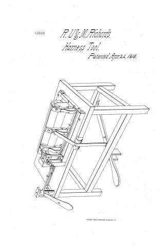
R. U. & M. Richards,
Harness Tool.
Patented Apr. 24, 1810.
Page 2.
Feb. 24, 1810
Robert W. Richardson & Mills Richardson
Letters Patent 1282X
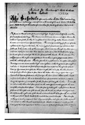
The Schedule refers to in their Letters Patent and making part of the same containing a description in the words of the said Robert W. Richardson and Mills Richardson themselves of a machine for making leather that is to be stitched.
The frame or Bench is two feet and a half high, two feet and a half wide, and three feet and four inches long. This frame would be more convenient for a shoemaker without legs or posts, for then he can place it on his cutting table, therefore it will be more convenient and less cumbersome. The carriage consisting of a frame of wood, eighteen inches long and ten wide, the running part of said carriage is iron or steel fastened to the under side of the carriage, which runs through iron steel or cast iron rods, five on a side. These rods are fastened in two sticks of timber lying each side of said carriage, the timber frames to the bench. On the above-mentioned Carriage on the right side is fastened two or three rings or gages made of steel with the notches upward. The clamps which are fastened on the upper side of said Carriage and are seven inches high and eighteen inches long, made of wrought iron cast iron in two parts, one part of said clamps is made fast on the left side of said Carriage by a cross piece of timber the same length of the clamps, the other part on side of clamps which is fixed to open, but at the bottom three iron gutters running in boxes which boxes are fastened in the Carriage, the lower part or bottom of the clamps are four inches apart, the side bars which are up and down are bent in order to bring the top bar or joins together for the purpose of holding the leather. The clamps are shut with three steel springs set in the carriage and a nest against the side bar of the clamps that opens. Clamps open by pulling the right foot on a treadle fastened at the right side of the bench, from the treadle is a strap which goes over the roller on the right side of the bench and reaches to the clamps with an iron hook on the end which hook hooks to the middle bar of said clamps. These clamps are hung in such a manner that they can be taken out after the leather is stitched and set on other benches and several use, therefore we deem it necessary if the business of the shop requires it to have a number of pairs of clamps fitted to run in one.
Page 3.
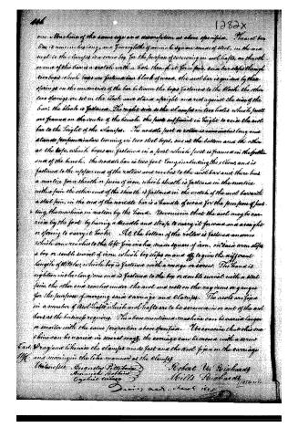
one a Machine of the same size on a description as above specified. The said bar box is nine inches long, and five eighths of an inch square mass of steel, in the area except in the clamps is a screw box for the purpose of screwing in and lofts, on the other end of the bar is a crutch with a hole through it for a pin, and a bar slips through two boxes which boxes are fastened in a block of wood, the said bar is guided by three springs on the underside of the bar between the boxes fastened to the block, the other two springs are set in the block once stand upright and rest against the side of the bar, the block is fastened. The right side is the clamps in two holes which parts are framed on the centre of the bench, the parts sufficient in height to raise the said bar to the height of the clamps. The movable part or roller is nine inches long and stands perpendicular turning in two steel boxes, one at the bottom and the other at the top, which boxes are fastened in a post which post is framed in the further end of the bench. The movable bar is two feet long including the elbow, and is fastened to the upper end of the roller and reaches to the said bar and there has a mortice for a sheath or piece of iron, which sheath is fastened in the mortice with a pin, the other end of the sheath is fastened in the crutch of the said bar with a steel pin, in the end of the movable bar is a handle of iron for the purpose of putting the machine in motion by the hand. I conceive that the said may be carried by the foot by having a handle and straps to carry it forward and a weight or spring to carry it back. At the bottom of the roller is fastened an arm which arm reaches to the left side in a box, made square of iron, on said arm slips a box or double screw of iron, which box slips on and off to give the different lengths of stitches, which box is fastened with a screw or screw. The hand is eighteen inches long, one end is fastened to the box or double screw with a steel pin, the other end reaches under the said and rests on the rag iron or gauges for the purpose of moving said carriage and clamps. The said are fixed in a number of said lofts which said lofts are to be screwed in or out of the said bars as the business requires. The above mentioned machine can be varied larger or smaller with the same proportion above specified. I conceive that this machine can be varied in several ways, the carriage can be moved with a screw and drag and likewise the clamps made fast and the said fixed on the carriage and moving in the like manner as the clamps.
Witnesses: Augustus Pritchard
Annwick Smith
Elizabeth Smith
Robert W. Pritchard
Mills Pritchard
Testa
Dated 18th June 1810
About this record
- Patentee
- Jim Shaw's X-patent list
- Date
- the Name and Date index of patents, USPTO records, Jim Shaw's X-patent list
- Invention
- the Name and Date index of patents
- Listed in
- the Name and Date index of patents, USPTO records, Jim Shaw's X-patent list, S. A. Elliot's printed list of patents, Burke's List of Patents (1847)
- S. A. Elliot's printed list of patents gives the same name and date.
- Burke's 1847 Patent Office list gives the same patent.
- Residence from Burke's 1847 Patent Office list; the standard lists give none.