

Drawings and documents
National Archives restored drawings: drawing
Russel H. Wright's Patent Drawing for a Regulated Windmill

National Archives, Restored Patent Drawings (Record Group 241) · Full-size scan at the National Archives · Catalog record
Show the text on the drawing Hide (80 words)
Words on the drawing as machine-read by the National Archives; not checked. Useful mainly for searching.
PNEUMATE / $150 / 1287-X / DIV SION / Prussel H Wright / Pregulated Wind mill. / Vol. 2. ps.477 / Patenter Apl.25. 1810. / OIR / Puferince. a.a. a ahrms. 6. 6.66 wornd / arms. a main shaft. d centre shaft. / b.k.d.ki horns. f. lean. g weight. / Patent affice April 19th 1845. / Inade under the dinotion of the Commisiony / correct Chimkeller, / of Patents in conformity with act of 3. march / 1834 / Mingh illmorth / Commits Bills of Putenty
USPTO scan
The patent as scanned by the USPTO
-
 Page 1
-
 Page 2
-
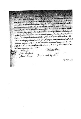 Page 3


U.S. Patent and Trademark Office · Google Patents
Show the transcription Hide (817 words)
Machine transcription (LightOnOCR) of the pages as scanned by the USPTO, most of them the handwritten copies made when the records were restored after the 1836 fire. Not checked; it can misread handwriting, so compare it with the scan.
Page 1.
F. H. Wright,
Wind Wheel.
Patented June 5, 1810.
NO. 1,287 - X
Page 2.
1287K 011 25300 April 28, 1810
Thomson Wright
Letters Patent
The Subscribed applied to me this Letter Patent and making part of the same containing a description in the words of the said Thomas Wright himself of his "Regulated Wind Mill."
The invention of this improvement called the Regulated Wind Mill, consists in constructing the arms of the Windmill on which the wind sails are put in such a manner as to have the mill regulate itself, so that let the wind hard or gently blow, the sails will go steady and regular. To effect this, the four arms on which the sails are fixed having the greatest half of said sails to the windward of said arms are made of round iron or hard wood & filled with boxes on the same arms, so as to turn about 70 rounds, by which means the angle of the wind sails is lessened in proportion to the increasing strength of the wind, and as said angle lessens, the less the wind affects the said sails. The round arms center at the shaft of the wind wheel, and the ends of them perpendicular arms at right angles with the said other parts of them. The main shaft of the same wheel is bored through it to a tube to contain an iron shaft, called the center shaft. On the outer end of this iron center shaft is permanently fixed the horns, made of iron. These horns are of each other at the center at right angles, and are welded together. The ends of said horns go into the ends of said round arms, and when said horns and the short arms of said round arms on which the sails are put, and close up to the end of the wind wheel shaft, which lies horizontally the said sails will be then turned horizontally the wind sails will be then turned sideways to the wind, and the wind wheel will then stop. To turn the said sails to the wind so as to have the same be not by it, a lever is fixed at the inner end of said iron center shaft, by which said shaft (on the outer end of which said horns are fixed) is drawn and ways so as to carry said horns out, and by these means to turn the sails to a proper angle with the wind, and the said said lever is connected proper ways to contain a sufficient weight which constantly presses said center iron shaft outward so as to keep said sails in a proper angle with the wind, in order to have the mill go as fast as may be wanted. If the wind blows harder, the said sails open their angle by forcing inward said horns and center shaft, which operation raises said weight and the mill thereby goes regular. When the wind blows moderately but not hard enough to raise said weight, the sails will then be kept at their general angle to the wind by said weight, so that by this improvement the wind mill may be made to go if the wind blows when wanted, & also stop just as easy, and regular as a water mill.
Page 3.
which splits the leather. A second square roller with the same width fitted to it, is placed into the frame round which the leather is drawn while splitting. The work which are movable on said square roller is so to prevent the leather from sticking. A piece of rubber with a groove is fixed with proper leather straps to this roller. Then the piece takes hold of the leather by turning said conical roller. They haul it through and as it is split, it then is wound round this roller. On one end of this conical roller a conical cone iron wheel two feet in diameter is firmly fixed. This conical wheel is turned by a pinion to which a crank is fixed by which the whole machine is made to operate. An other roller is also fixed on the frame so as to keep the leather while splitting up close to the surface of the cylinder. The roller under the edge of the knife and which forms the gauge is made of cast iron about five inch in diameter and is accurately turned. The three rollers are made of hard wood. The sides of Necks, cotton as well as shoddy and other skins, may be split by this machine as well as to make two skins out of one.
Witnesses:
John Fairbanks
Josiah Leving
Drawing made by A.B.
Filed:
1850 1027
About this record
- Patentee
- Jim Shaw's X-patent list
- Date
- the Name and Date index of patents, USPTO records, Jim Shaw's X-patent list
- Invention
- the Name and Date index of patents
- Listed in
- the Name and Date index of patents, USPTO records, Jim Shaw's X-patent list, S. A. Elliot's printed list of patents, Burke's List of Patents (1847)
- S. A. Elliot's printed list of patents gives the same name and date.
- Burke's 1847 Patent Office list gives the same patent.
- Residence from Burke's 1847 Patent Office list; the standard lists give none.