

Drawings and documents
National Archives restored drawings: drawing
Briggs R. Reid Patent Drawing for a Nail Cutting Machine

National Archives, Restored Patent Drawings (Record Group 241) · Full-size scan at the National Archives · Catalog record
Show the text on the drawing Hide (102 words)
Words on the drawing as machine-read by the National Archives; not checked. Useful mainly for searching.
85. METAL WORKING, / 4se / Cut Nail M'k'g. / ing. / Briggs R. Reid / CLASSIFICATION / Nail buiting Machine. / Patent any. 18. 1810.X / 1358-X / DIVISION. / Vol.2. ps. 413 / Nail butting Moachin / in / B- / Headers alide tally / through a grove and / the heads by pressure and / This conneyor and you, contre / groove by which a spring catel / the blank siger and transferred to the grephers- / and the commy / sohen the Cutter rises / relanguishes it / Patent affice haren 5 1845 / Instruntu the dicotion of oh Company / Catent in conformity with actifs.Imm 100y / Hany / Correct
USPTO scan
The patent as scanned by the USPTO
-
 Page 1
-
 Page 2
-
 Page 3
-
 Page 4
-
 Page 5
-
 Page 6
-
 Page 7


U.S. Patent and Trademark Office · Google Patents
Show the transcription Hide (1,392 words)
Machine transcription (LightOnOCR) of the pages as scanned by the USPTO, most of them the handwritten copies made when the records were restored after the 1836 fire. Not checked; it can misread handwriting, so compare it with the scan.
Page 1.
1358X
B. R. Reid,
Making Cut Nails,
Patented Aug. 18, 1810.
Sheet 1-3 Sheets.
Page 2.
1358X
Sheet 2-3 Sheets.
B. R. Reid,
Making Cut Nails,
Patented Aug. 18, 1810.
Page 3.
1358X
Sheet 3-3/Sheet
B. R. Reid,
Making Cut Nails,
Patented Aug. 18, 1810.
Page 4.
Aug 16, 1865 47.
Buggs Rogers Reid 1358X
Batters Patent
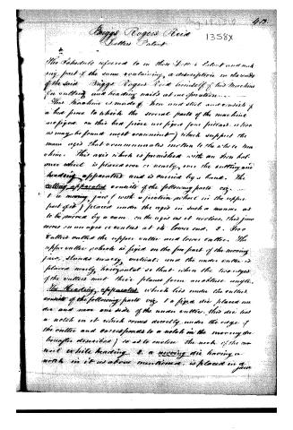
The Schedule referred to in these Buggs Patent and making part of the same containing a description in the words of the said Buggs Rogers Reid himself of his machine for cutting and heading nails at one operation.
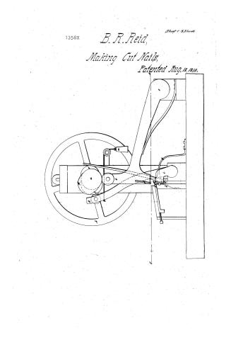
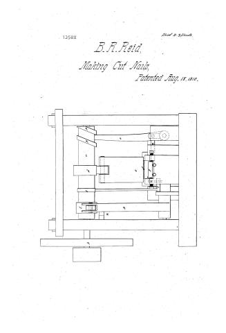
This Machine is made of iron and steel and consists of a bed piece to which the several parts of the machine are fixed on this bed piece are fixed four pillars, or like as may be found most convenient) which support the main axis that communicates motion to the whole machine. This axis which is furnished with an iron balance wheel is placed over or nearly over the cutting and heading apparatus and is carried by a hand. The cutting apparatus consists of the following parts viz. 1. a moving jaw (with a friction wheel in the upper part of it) placed under the axis in such a manner as to be moved by a cam on the axis as it revolves, this jaw moves on an axis or centres at its lower end. 2. Two cutters called the upper cutter and lower cutter. The upper cutter revolves as fixed on the fore part of the moving jaw, stands nearly vertical, and the under cutter is placed nearly horizontal so that when the two edges of the cutters meet their planes form an obtuse angle.
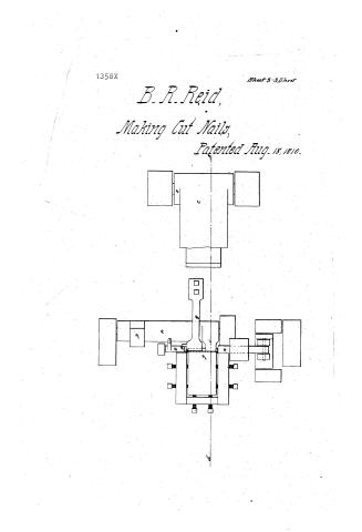
The Heading apparatus which lies under the cutters consists of the following parts viz. 1. a fixed die placed under and near one side of the under cutter. This die has a notch in it which comes directly under the edge of the cutter and corresponds to a notch in the moving die hereafter described) so as to enclose the notch of the moving die while heading. 2. a moving die having a notch in it as above mentioned, is placed in a jaw
Page 5.
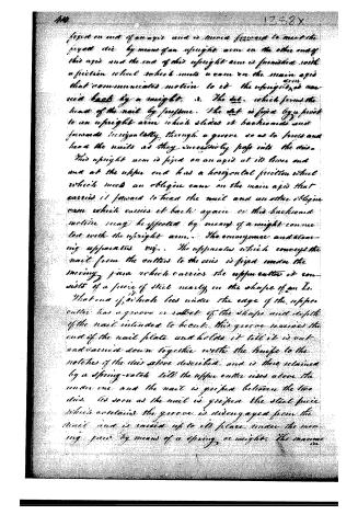
fixed on end of an axis and is moved forward to meet the fixed die by means of an upright arm on the other end of this axis and the end of this upright arm is furnished with a friction wheel which meets a cam on the main axis that communicates motion to it. The upright arm is moved back by a weight. 3. The die, which forms the head of the nail by pressure. The die is fixed by a pivot to an upright arm which slides it backwards and forwards horizontally through a groove so as to force and head the nails as they successively pass into the dies.
This upright arm is fixed on an axis at its lower end and at the upper end has a horizontal friction wheel which meets an oblique cam on the main axis that carries it forward to head the nail and an other oblique cam which carries it back again. Or this backward motion may be effected by means of a weight connected with the upright arm. The conveyance and cleaning apparatus viz. The apparatus which conveys the nail from the cutter to the dies is fixed under the moving jaw which carries the upper cutter it consists of a piece of steel nearly in the shape of an I. That end of which lies under the edge of the upper cutter has a groove or socket of the shape and depth of the nail intended to be cut. This groove receives the end of the nail plate and holds it till it is cut and carried down together with the knife to the notches of the dies above described, and is there retained by a spring-catch till the upper cutter rises above the under one and the nail is gripped between the two dies. As soon as the nail is gripped the steel piece which contains the groove is disengaged from the nail and is raised up to its place under the moving jaw by means of a spring or weight. The manner...
Page 6.
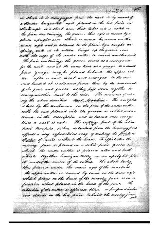
in which it is disengaged from the nail is by means of a slender horizontal axis placed in the bed piece on which axis is a short arm that takes into a notch in the piece containing the groove. This axis is moved by a slender upright arm which is moved by a cam on the main axis and is returned to its place by a weight or spring and in its return brings up the groove even with the edge of the under cutter to receive another nail. The piece containing the groove serves as a conveyance for the nail and at the same time as a gauge as a small fixed gauge may be placed behind the upper cutter after a nail is cut and conveyed to the vise and headed it is cleared from them by the movement of the jaw and groove as they pass down together to convey another nail to the vise. The manner of using the above described Nail Machine. The nail plate is held by the workman on the face of the under cutter, with the end placed into the groove or rabbit mentioned in the description and is turned once every time a nail is cut. The cutting part of the above Nail Machine when detached from the heading part affords a very inexpedient way of making the points in shape of nails without the heads. To effect this the moving jaw is placed on a solid piece of iron on which the under cutter is placed also and both vibrate together horizontally on an upright pin at under the centre of the cutters. The whole being then placed under the main axis of the machine. The upper cutter is moved by cams on the same axis which plays on the head of the moving jaw, or on a friction wheel placed in the head of the jaw. The vibration of the cutter is effected thus: a perpendicular axis stands on the bed piece behind the moving jaw and
Page 7.
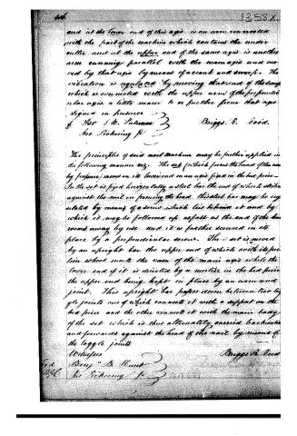
and at the lower end of this axis is an arm connected with the part of the machine which contains the under cutter and at the upper end of the same axis is another arm running parallel with the main axis and moved by that axis by means of a crank and swivel. The vibration is regulated by moving that end of the lever which is connected with the upper arm of the perpendicular axis a little nearer to or further from that axis.
Signed in presence of
Rev. J. M. Putnam
Jno. Pickering Jr.
Briggs R. Reid.
The principles of said nail machine may be further applied in the following manner viz. The set (which forms the head of the nail by pressure) moves on its lower end on an axis fixed in the bed piece. In the set is fixed horizontally a steel bar the end of which strikes against the nail in forming the head. This steel bar may be regulated by means of a screw which lies behind it and by which it may be followed up as fast as the end of the bar recedes away by use and it is further secured in its place by a perpendicular screw. The set is moved by an upright bar the upper end of which with its peculiar wheel marks the case of the main axis while the lower end of it is directed by a nut in the bed piece. The upper end being kept in place by an arm and joint. This upright bar passes down between two large joints one of which connects it with a support on the bed piece and the other connects it with the main body of the set which is thus alternately carried backwards and forwards against the head of the nail by means of the laggle joints.
Witness
Benj. B. Hunt
Jno. Pickering Jr.
Briggs R. Reid.
About this record
- Patentee
- Jim Shaw's X-patent list
- Date
- the Name and Date index of patents, USPTO records, Jim Shaw's X-patent list
- Invention
- the Name and Date index of patents
- Listed in
- the Name and Date index of patents, USPTO records, Jim Shaw's X-patent list, S. A. Elliot's printed list of patents, Burke's List of Patents (1847)
- S. A. Elliot's printed list of patents gives the same name and date.
- Burke's 1847 Patent Office list gives the same patent.