

Drawings and documents
National Archives restored drawings: drawing
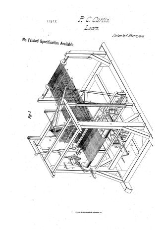
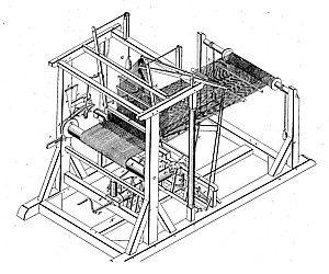
Clinton Curtis' Patent Drawing for a Water Loom

National Archives, Restored Patent Drawings (Record Group 241) · Full-size scan at the National Archives · Catalog record
Show the text on the drawing Hide (280 words)
Words on the drawing as machine-read by the National Archives; not checked. Useful mainly for searching.
Clinton Curtis' / WATER LOU / Paten ted November17, 1810. / Reference / Fig.1. Fio: @ 1. / vol. Vol.2nd page / Fig. 1. Represents a common Loom formentioned / in specification) and the parts lettered, are in / accordance with specification; which are,to wit.- / A, The cloth roller or beam. / B,B,- The Shuttle boxes / C, Lathe or Batten, / 1391.7 / d,d, The treadles - / E- grooved cylinder. / F'- winch or handle, / H, permanent ratchet or taking up wheel, / K, movable ratchet wheel; / l, spring. / m,m, palls or hands / n, virtical break.- / p,p, the springs: / q, balance lever- / r,r, cords:- / n', horizontal pitman / S,S, vertical bars of batten, / t,t, virtical levers. / N, horizontal beam / и.и, pins / v, spiral groove / w,w, weights cords pulleys / x,x, chains / a, upright roller / b,3, arms; / E,E, transverse bars, / f- an arm for giving motion to the shuttle / Patent Office / g,g,- frame for moving the Batten backward preparatory to the stroke: / July 12. 1845. / h, sill or bar turning on pivots- / i,i, bars having their upper end connected with the Batten C, by the / made under the direction of the Commissioner / rods 0,0,.. / of Patents in conformity with the act of / M,M, upright bars- / 32 of March 1837 - / x'x',- projecting pins which move in the grove D, on the cylinder E;- / G,G, wrights for moving the lathe or Batten forward / Ellment Durke / P.P. wheels with bevel gened teeth; / Q1, vertical roller with groove & pins for moving the treadles d,d,.- / Commisimer of Patents / Drawn from specification by August.A. Von Bhmidt
USPTO scan
The patent as scanned by the USPTO
-
 Page 1
-
 Page 2
-
 Page 3
-
 Page 4
-
 Page 5


U.S. Patent and Trademark Office · Google Patents
Show the transcription Hide (1,128 words)
Machine transcription (LightOnOCR) of the pages as scanned by the USPTO, most of them the handwritten copies made when the records were restored after the 1836 fire. Not checked; it can misread handwriting, so compare it with the scan.
Page 1.
1391X
P. C. Curtis.
Loom.
Patented Nov. 17, 1810.
No Printed Specification Available
Fig. 1.
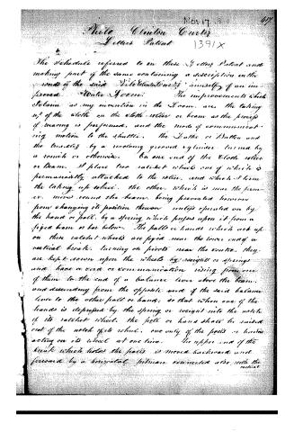
Page 2.
The Schedule referred to in these Letters Patent and making part of the same containing a description in the words of the said William Clinton Curtis himself of an improved "Wale Frame." The improvements which I claim as my invention in the Frame, are, the taking up of the cloth on the cloth-roller or beam as the process of weaving is performed, and the mode of communicating motion to the shuttle. The Shuttle or Button and the bobbins by a revolving groove cylinder turned by a worm or otherwise. On one end of the Cloth roller or Beam, I place two ratchet wheels one of which is permanently attached to the roller, and which I term the taking up roller. The other, which is near the former, moves round the beam, being prevented however from changing its position thereon unless operated on by the hand or foot, by a spring which presses upon it from a fixed beam or bar below. The feet or hands which act up on these ratchet wheels are fixed near the lower end of a vertical beam, turning on pivots near the centre. They are kept down upon the wheels by weights or springs and have a cord or communication rising from one of them to the end of a balance lever above the beam, and descending from the opposite end of the said balance lever to the other foot or hand; so that when one of the hands is depressed by the spring or weight into the notch of its ratchet wheel, the foot or hand shall be raised out of the notch of its wheel, one only of the feet or hands acting on its wheel at one time. The upper end of the beam which holds the feet is moved backward and forward by a horizontal piston connected also with the vertical
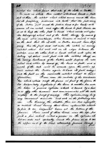
Page 3.
vertical bar which forms that side of the Lathe or Batten.
The mode in which these catch-wheel and hands or pallets act is this: the catch-wheel which moves round the beam has its periphery so divided into teeth that the full swing of the Batten just misses the pallet or hand so far back as to remove it one notch and suffer the hand to fall therein, and so as to help the other pallet or hand which would act upon the taking-up wheel out of the teeth thereof, by means of the rack above mentioned, when however so much is worn on the rack that the Lathe or Batten cannot have its full swing, then the pallet does not enter the notch in moving catch-wheel but will rest on its edge between the notches, and the other pallet or hand which acts upon the taking-up wheel will fall into the notches thereof, and the moving backward of the batten will project the catch-wheel and roller by means of the hand or pallet, and so much of the rack will be worn upon the roller as will allow the Batten again to have its full swing, and the pallet on the movable catch-wheel to have operation.
From near the middle of the transverse bar which crosses across the frame in front of the loom, there lies horizontally lengthwise of the loom to another bar under the batten, a grooved cylinder which is turned by a hand or in any other manner, and communicates all the motion necessary to the process of weaving. This cylinder may be of any convenient diameter, and acts in the following manner. For throwing the shuttle, there are two upright or vertical levers having their lower extremities attached by pins to an horizontal beam at the bottom of the frame. From each of these levers, near the top, projects a pin which enters a groove in the cylinder which has one side cut spirally round the frame so as to move the upper end of the levers alternately forward towards the front.
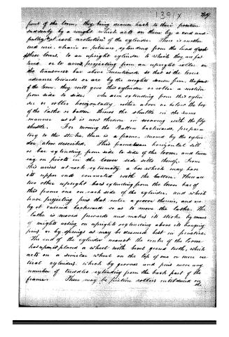
Page 4.
front of the loom, they being drawn back to their position suddenly by a weight which acts on them by a cord and pulley at each revolution of the cylinder. There is another cord wire, chain or filament extending from the head of each of these levers, to an upright cylinder to which they are fastened, or to arms projecting from an upright roller on the transverse bar above mentioned, so that as the levers advance towards or are by the weights drawn from, the front of the loom, they will give this cylinder or roller a motion from side to side. An arm extending from this cylinder or roller horizontally either above or below the boy of the lathe or batten throws the shuttle in the same manner as it is now thrown in weaving with the fly shuttle. For moving the batten backwards, preparatory to the stroke, there is a frame, moved by the cylinder above described. This frame has an horizontal sill or bar extending from side to side of the loom, and turning on pivots in the lower side sills thereof. From this wires at each extremity a bar which may have its upper end connected with the batten. There are two other upright bars extending from the lower bar of this frame one on each side of the cylinder, and which have projecting pins that enter a groove therein, and are by it raised backwards so as to move the lathe. The lathe is moved forwards and makes its stroke by means of weights acting on uprights extending above its hanging pins or by springs as may be deemed best in practice. The end of the cylinder nearest the centre of the loom has upon it placed a wheel with bevel gear teeth, which acts on a similar wheel on the top of one or more vertical cylinders, which by grooves and pins move any number of treadles extending from the back part of the frame. There may be friction rollers mounted on the
Page 5.
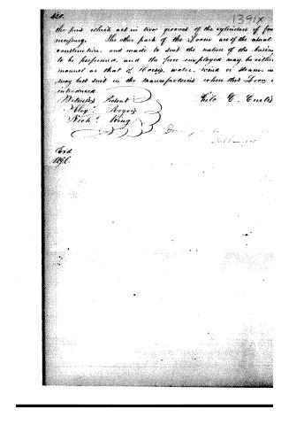
the pins which act in two grooves of the cylinders of the machinery. The other parts of the loom are of the usual construction, and made to suit the nature of the business to be performed, and the force employed may be either manual or that of horses, water, wind or steam, as may best suit in the manufactures where this loom is introduced.
Witnesses Present:
Wm. Rogers
Nich. King
Filed U. C. Curtis
Dated: 1844
Filed
1846.
DATAMP: illustration
Illustrations from DATAMP

DATAMP (Directory of American Tool and Machinery Patents), via the Internet Archive · Archived DATAMP page
About this record
- Patentee
- DATAMP
- Date
- the Name and Date index of patents, DATAMP, USPTO records
- Invention
- DATAMP
- Listed in
- the Name and Date index of patents, DATAMP, USPTO records, Jim Shaw's X-patent list, S. A. Elliot's printed list of patents, Burke's List of Patents (1847)
- S. A. Elliot's printed list of patents gives the same name and date.
- Burke's 1847 Patent Office list gives the same patent.