

Drawings and documents
USPTO scan
The patent as scanned by the USPTO
-
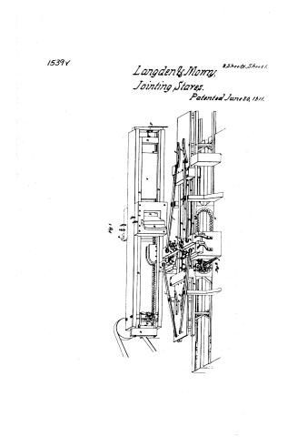 Page 1
-
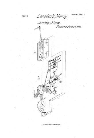 Page 2
-
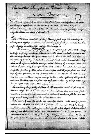 Page 3
-
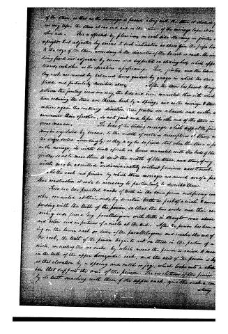 Page 4
-
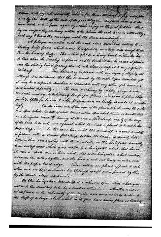 Page 5
-
 Page 6


U.S. Patent and Trademark Office · Google Patents
Show the transcription Hide (1,438 words)
Machine transcription (LightOnOCR) of the pages as scanned by the USPTO, most of them the handwritten copies made when the records were restored after the 1836 fire. Not checked; it can misread handwriting, so compare it with the scan.
Page 1.
1539V
Langden & Morry,
Jointing Staves.
Patented June 20, 1811.
2 Sheets. Sheet 1.
Fig. 1
<!-- Image content: Technical drawing of a mechanical device labeled "Fig. 1" showing a complex assembly with gears, levers, and structural frames. -->
Page 2.
1539X
Langden & Morry,
Jointing Stares.
Patented June 20, 1811.
2 Sheets, Sheet 2.
Fig. 3
Fig. 4
A.M. PHOTO-LITHS. CO. N.Y. (OSBORNE'S PROCESS)
Page 3.
Barnabas Langdon and William Murray.
Letters Patent.
The schedule referred to in these Letters Patent and making part of the same containing a description in the words of the said Barnabas Langdon and William Murray themselves of their Machine, for shaving, jointing, and forming the staves and heads of barrels &c.
This Machine consists of the following parts viz. The machinery for shaving and dressing the staves: - the machinery for jointing: - and the machinery for dressing, dovelling and cutting the heading -
The machinery for shaving and dressing staves, is composed of two planestocks standing vertically, with any number of plane-irons either double or single, the irons on one side sounding the outer side of the staves, and the irons on the other side following it, agreeably to the size of the cask or barrel to be formed. The rough stave being placed on its edge on a sliding carriage which traverses by means of a double rack and pinion between, or by means of a single rack or slide carried back by a weight, is, by the operation of these plane irons, dressed into its proper form and thickness by one operation, or once passing between the stocks. The stocks in which the plane irons are placed, may be made of metal, or other sufficiently strong material; and the plane irons are fixed and adjusted in them by screws descending from the upper surface upon their edges.
The machinery for jointing is placed in the same line with the former, so that a carriage moved by the same rack and pinion may answer, or if circumstances render it more convenient, a separate rack and pinion, and carriage may be used, at the option of the constructor.
Perpendicularly over the rack, and attached thereto, is the carriage for receiving and holding the stave to be jointed. The carriage stands vertically, and has a movable upper jaw extending its whole length between which and a fixed horizontal under jaw the stave is laid with the concave side downwards. It is held in the position by a wedge, screw or lever. On the upper part of this carriage are grooves formed corresponding to the seams or bights.
Page 4.
of the stone, so that as the carriage is passed along with the stone, it shall in one way taper the stone at one end and in the return of the carriage taper it on other end. This is effected by plan iron on each side standing on joints upright, but adjusted by screws to such inclination as shall give the proper line to the edge of the stone, according to the diameter of the barrel or cast. The iron being fixed and adjusted by screws are supported on sliding bars which oppose towards each other as the operation is performing. The joints, and the bottom key cast, are moved by balanced levers guided by grooves in which the stone stands, and particularly described above. After the stone has passed through between the jointing irons one way, the bars and irons connected therewith which have reduced the stone are thrown back by a spring, and as the carriage & stone return again the contrary direction these joints are released, and another commences their operation, so as to joint and taper the other end of the stone in the same manner.
The heads of the sliding carriages, which support the joint, may be regulated by screws, to the widths of certain descriptions of stones, and the stages sorted accordingly; or they may be so fixed that when the stone is put in the carriage, its width shall operate on levers connected with the beds of the joints, so as to move them to suit the width of the stone, and stones of any width may be admitted indiscriminately without previous ascertainment.
As the rack and pinion by which these carriages are moved are of a peculiar construction it will be necessary to particularly describe them.
There are two parallel racks of teeth in the same frame and facing each other, connected at their ends by similar teeth in part of a circle & corresponding with the teeth of the pinion, so that the two racks and their connecting ends form a long parallelogram with teeth in straight rows above and below and in portions of a circle at the end. After the pinion has been acting on the lower rack or side of the parallelogram and reaches the end of the rack, the teeth of the pinion begin to act on those in the portion of a circle, connecting the two racks, by which means the pinion is raised to meet in the teeth of the upper horizontal rack, and the axis of the pinion is kept at that elevation by a spring and catch or jaw, which locks into a slot in the bar that supports the axis of the pinion. The revolutions of the pinion by its teeth meshing with those of the upper rack, give the rack a con-
Page 5.
motion to its opposite extremity, when a pin throws the rack or peg out of place and by the teeth of the one of the parallelogram the pinion descends to the lower track, and is fixed again by a catch or peg in the first position. Thus by an uniformly revolving motion of the pinion the rack traverses alternately, each way & bears the carriages with the claws accordingly.
A fulcrum connected with the rack above described extends to a sliding knife frame which moves horizontally in a box wide enough to contain the heading stuff. This is laid flat on a rising bench within the box so that when the heading is placed on the bench, it can be raised at pleasure and the sliding knife passing over it, will then of drop it to any required thickness. These knives may be placed with any degree of slippage, and although it is mentioned that this is moved by the racks before described, yet it may be a separate machine or connected with any other of its movements and worked separately. The same machinery by adding quays to raise the bench and by substituting the proper planes, will serve to plane chips for hats, splits for boxes & other purposes and we hereby describe it accordingly.
On the inner end of the axis of the pinion which moves the rack is a spur wheel, the teeth of which turns another spur wheel pinion or toothed head on a horizontal mandrel, having at its end a flat clamp nearly of the size of the head to be cut, and against which the head is placed to be cut to the proper size. In the same line with this mandrel is a screw mandrel or follower with a similar flat clamp, so that the heading is equally held between them and revolving with the mandrel, on this horizontal mandrel is an endless screw which gives motion to a horizontal wheel, that has on its axis a small, iron or bone wheel, that rolls the horizontal wheel revolving, advances the cutter together, and the head is cut out truly circular and with the proper level edge. These cutters are placed opposite to each other and are kept asunder by springs except when pressed together by the nail above mentioned.
On this horizontal mandrel is a whorl or spur wheel which gives motion to the dowelling bits, by a band or otherwise. Another wheel or whorl placed in the extremity of the pinion axis communicates motion to the shaft of a large wheel which in its free brass having planes or hatches
Page 6.
for the purpose of trimming any kind of Cooper stuff.
We propose the foregoing machinery, or machinery of the same
plan, or parts thereof, to the trimming and preparation of every description
of Cooper stuff, and consider the same as part of our discovery and
Invention.
William Thornton
in Lyon
Barnabas Langdon
William Mooney
Drawing Made
1808
E.2
Cly.W.
DATAMP: illustration
Illustrations from DATAMP

DATAMP (Directory of American Tool and Machinery Patents), via the Internet Archive · Archived DATAMP page
About this record
- Patentee
- DATAMP
- Date
- the Name and Date index of patents, DATAMP, USPTO records
- Invention
- DATAMP
- Listed in
- the Name and Date index of patents, DATAMP, USPTO records, Jim Shaw's X-patent list, S. A. Elliot's printed list of patents, Burke's List of Patents (1847)
- S. A. Elliot's printed list of patents gives the same name and date.
- Burke's 1847 Patent Office list gives the same patent.