

Drawings and documents
National Archives restored drawings: drawing
Abraham Norton's Patent Drawing for a Increasing Press

National Archives, Restored Patent Drawings (Record Group 241) · Full-size scan at the National Archives · Catalog record
Show the text on the drawing Hide (76 words)
Words on the drawing as machine-read by the National Archives; not checked. Useful mainly for searching.
[46] Cheese. / Packers / Presses - Theese pref / /150 / CLASSIFICATION / 1663.7 / ABRAHAM NORTON / DIVISION. / Increasing Brefs: / Patented / A. Horizontal sills / B. rertical Posts / C. Bench. / D. Pressing Beam / E. Follower or prefser / F'. Lever / IF / G. Crank Vertical Post= / and Lever / BL / Patent Office yth July 1838, / Made under the direction of the Commissioner / of Patents in conformity with act 3d March 1857 / Commissioner of Patents,
USPTO scan
The patent as scanned by the USPTO
-
 Page 1
-
 Page 2
-
 Page 3


U.S. Patent and Trademark Office · Google Patents
Show the transcription Hide (799 words)
Machine transcription (LightOnOCR) of the pages as scanned by the USPTO, most of them the handwritten copies made when the records were restored after the 1836 fire. Not checked; it can misread handwriting, so compare it with the scan.
Page 1.
1663X
A. Norton,
Cheese Press,
Patented Feb. 11, 1812.

A.M. PHOTO-LITHO. CO. N.Y. (OSBORNE'S PROCESS)
Page 2.
Feb. 11, 1812
1663X
129
Abraham Martin
Letters Patent
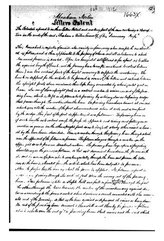
The Schedule referred to in these Letters Patent and making part of the same containing a description in the words of the said Abraham Martin himself of his "Innovating Refs."
This Press which is capable of providing a variety in form, may when simple be constructed as follows and is then applicable to the pressing of cheese and all substances to which low mean pressure is applied. Upon two horizontal rails placed so far apart as to allow the required length of bench, and the pressing beam hereafter mentioned to extend between them) rise two vertical posts of the height necessary to support the machinery. The bench or support for the articles to be pressed is nearest the bottom and extends between the upright posts above mentioned their tops being connected by a horizontal girder or brace. In one of these upright posts is a vertical motion to receive one end of the pressing beam, which is kept in its place while pressing by a triangular or tapering wedge that passes through the motion above the beam. The pressing beam has a tenant at one end, which goes into the motion of the post above mentioned when it rests and is confined by the wedge. This part of the post supporting it as a fulcrum. The pressing beam is of such length as to extend among the posts its opposite end rising and falling in a motion or groove in the other upright post so as to keep it steady when raised or lowered by the lever herein described. There is a motion through this pressing beam through which rises the upper end of the follower or presser. This follower also goes through a motion in the upper girder so as to preserve direct motion. The pressing beam lays upon a projecting shoulder in the presser or follower, so that as it descends it bears down the presser with it, and by means of a pin which goes horizontally through the beam and presser, the latter rises as the beam is elevated from the article which has been subjected to pressure.
Above the presser lies the lever by which the power is applied. Its fulcrum or pivot is a screw passing through the vertical post above the moving end of the pressing beam. This fulcrum is let in a staple bolt one fork or forked piece of which goes through the post the other through the lever beneath, the width of this motion being required distance according to the power wanted when it receives a crank connected with the movable end of the pressing, so that as the lever is raised or depressed it raises or bears down the end of the pressing beam connected therewith and then by the presser or follower which is between the end of the pressing beam that moves and the end which
Page 3.
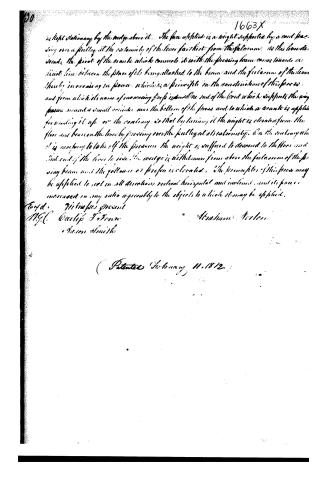
is kept stationary by the weight above it. The face of the lid is a weight supported by a cord passing over a pulley at the extremity of the lever farthest from the fulcrum. As this handle descends, the pivot of the crank which connects it with the pressing beam comes towards a fixed line between the place of its being attached to the beam and the fulcrum of the lever thereby increasing in power, which is a principle in the construction of this press, and from which its name of increasing prop is derived. One end of the cord which supports the way passes round a small cylinder near the bottom of the press and to which a crank is applied for winding it up or the contrary, so that by turning it the weight is elevated from the floor and bears on the lever by pressing over the pulley at its extremity. On the contrary when it is necessary to take off the pressure the weight is suffered to descend to the floor and that end of the lever to rise, the weight is withdrawn from above the fulcrum of the pressing beam and the follower or press is elevated. The principles of this press may be applied to use in all directions vertical horizontal and inclined, and its power increased in any ratio agreeably to the objects to which it may be applied.
Eryd. Witness present
N.G.C. Carlip F. Fenn
Jason Smith
Abraham A. A. A.
(Patented February 11, 1812.)
About this record
- Patentee
- Jim Shaw's X-patent list
- Date
- the Name and Date index of patents, USPTO records, Jim Shaw's X-patent list
- Invention
- the Name and Date index of patents
- Listed in
- the Name and Date index of patents, USPTO records, Jim Shaw's X-patent list, S. A. Elliot's printed list of patents, Burke's List of Patents (1847)
- S. A. Elliot's printed list of patents gives the same name and date.
- Burke's 1847 Patent Office list gives the same patent.