

Drawings and documents
USPTO scan
The patent as scanned by the USPTO
-
 Page 1
-
 Page 2
-
 Page 3
-
 Page 4
-
 Page 5


U.S. Patent and Trademark Office · Google Patents
Show the transcription Hide (1,594 words)
Machine transcription (LightOnOCR) of the pages as scanned by the USPTO, most of them the handwritten copies made when the records were restored after the 1836 fire. Not checked; it can misread handwriting, so compare it with the scan.
Page 2.
United States Patent
Patent No.: X1690
Mellen Battle
Letters Patent, Patented November 6, 1829.
The Schedule referred to in these Letters Patent, & making part of the same, containing a description, in the words of the said Mellen Battle himself, of his improvement in Steam engines.
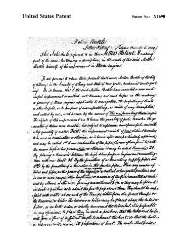
To all persons to whom these presents shall come, Mellen Battle of the City of Albany, in the County of Albany and State of New York, Mechanist and Engineer: Be it known, that I, the said Mellen Battle have invented a new and useful improvement or method not known, nor used before in the making or forming of Steam engines applicable to navigation, the propelling of Boats or other Vessels, or to purposes of manufacturing, or Mills of any description, and called by me, and known by the name of "The reciprocating Steam engine." The objects of this improvement are to lessen the quantity of fuel, to make the generator of steam more durable, less subject to explosion, more powerful, and with a less quantity of water. First, this improvement consists of four distinct branches, to be used in combination, or otherwise, as is herein after more particularly explained, and may be called 1st A new combination of the pipes (herein after referred to) with the common high or low pressure boiler or otherwise it may be called Reservoirs: 2d By placing a Reservoir between the high & low pressure Engines and connecting them with one shaft. 3d By the formation of a Generating supply pipes, and 4th by the formation of a Generator in the smoke pipe. Place any number of tubes and pipes, as the power of the engine, in a vertical or horizontal position, and in one or more ranges, either lengthwise or crosswise of the fire, connected at each end by elbows, or otherwise, forming one continued pipe, or they may be placed in such a position as to admit the fire to pass about them. They should be supplied with water at one end of the Ranges, either from the forced Pumps, or the Reservoir, or boiler. The reservoir or boiler may be placed above the tubes or below, or on both sides, or wholly surround the tubes, but, it is preferable in my opinion, to place them in such a position, that the tubes and boiler, will form a flue of sufficient length to exhaust the heat, so that the boiler, or reservoir will receive its proportion of heat. The water that passes
Page 3.
United States Patent
Patent No.: X1690
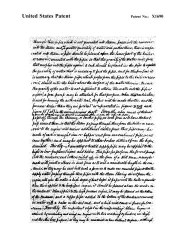
through these pipes, which is not generated into steam, passes into the reservoir with the steam, and a greater quantity of water will gather there, than is evaporated into steam, a pipe should be placed upon the lower part of the boiler or reservoir, connected with the pipes, so that the gravity of the water will force that overplus into the pipes again. A cock should be placed in the pipe to regulate the quantity of water that is necessary to feed the pipes, and for this purpose it is necessary, that the steam pipe, which passes from the pipes to the boiler or reservoir, should enter the boiler above the surface of the water therein. In case the gravity of the water is not sufficient to return the water into the pipes again, a force pump may be attached for that purpose. When this combination is used for burning the anthracite coal, the fire will be made shorter, and the furnace deeper than they are for wood as represented in figure D [7] and figure H [40] in the accompanying draft. Secondly, when much of the heat passes off, through the chimney, or smoke pipes, in such form as to have the heat pass around them, so that the steam passing through them from the boiler or reservoir to the engine will receive additional elastic force. These pipes may be made of cast or wrought iron or copper, and form one continuous pipe, or all come together, and may be applied to other boilers distinct from the before described. Thirdly, a generating or heated supply pipe may be applied to the high or low pressure engine and boilers. This pipe passes from the forced pump into the condenser, and is there coiled up in the form of a still drum, or may be made with joints or elbows in such form as to coil a considerable length in the condenser, or they may be cast into such a form as to make one coiled pipe so that the supply water passing through these pipes with the steam flowing direct from the engine, will give the water a high degree of heat before it passes into the boiler or generator. When this is applied to the low pressure engine, it should be placed above the water in the condenser. When applied to the high pressure engine, it may be placed at the bottom of the condenser, and a copper pipe added to the bottom of the condenser immersed in water with a valve in the out end, and which will cause a powerful vacuum. Fourthly, the important object in the reciprocating Steam Engine is attained by constructing and using an engine with two working cylinders, one high and the other low pressure, or they may be considered as two distinct engines, although
Page 4.
United States Patent
Patent No.: X1690
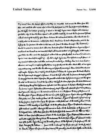
they cannot have, the desired effect, unless they are connected and one uses the steam from the other, and assists the other across what is termed the dead point, and the low pressure receives the steam from the high, but instead of receiving it direct as the Wolf Engine does, it pipes into a reservoir of suitable size, to have the steam expand with suitable elasticity, to work the low pressure cylinder, without reducing the elasticity of the steam between the intermediate strokes. There should also be a safety valve in the reservoir, so that if the steam should rise to such a temperature, as to be too high for the low pressure, the valve in that case, will permit the steam to escape. This reservoir should be enclosed or surrounded with a non-conductor of heat. The two cylinders or engines, before mentioned are to work on one connected shaft with cranks to stand at right angles, so that one engine takes the other across the dead point without the use of the fly wheel, or at most it will not require more than half the weight of fly, that a single engine does. These cylinders may be placed at any convenient distance from each other, and may be worked by a Walking beam or a cross head or otherwise, and may be so coupled together that one may operate, and the other stand still, or one engine may work one way, and the other the other way, as is frequently necessary in steam boats to turn short at right angles. To perform this, a coupling should be placed between the engines, upon the crank shaft so that the engines may be disengaged at pleasure. To work the high without the low pressure, the coupling should be disengaged and the steam to pass from the generator or boiler to the high pressure engine and blow off at the valve on the reservoir. To work the low without the high, the steam passes from the boiler to the reservoir, without passing through the high pressure cylinder, and there expands to its proper elasticity to work the low pressure engine. Explanation of the accompanying draft Figure A represents a front view of the combined generator showing 1.1.1. The reservoir or boiler 2.2.2.2. The pipes 3. The doors of the furnace 4. The steam pipe. Figure B represents the end view of the high pressure engine showing 5. The cylinder 6. The piston rod. 7. The walking beam 8. The reservoir. Figure C represents a front view of the low pressure engine showing 9. The cylinder 10. The piston rod. 11. The walking beam 12. The condenser 13. The connecting or crank shaft 14. 14. the gellnor frame. Figure D represents a side view of the combined generator, showing 15. the reservoir or boiler 16. the heated pipe 17. the furnace 18. the horizontal tubes 19. the steam pipe from the heated pipe to the reservoir 20. 20. The air the bottom or lower part of the reservoir at back 21. the smoke pipe. Figure E represents the condenser and heated supply pipe showing 22. 22. The condenser 23. the heated pipe. Figure F represents a side view of the double engine showing 24. The walking beams 25. the cylinder (low pressure) 26. The Valve. Raising 27. The Gellnor .... frame 28. the air pump 29. the fore pump 30. the fly wheel 31. brakes. Figure G represents a front view of the generating, smoke pipe together with a boiler.
Page 5.
United States Patent
Patent No.: X1690
for low pressure or loco motive Engine. 32 the generating smoke pipes. 33 the reservoir for steam and water. 34, 34. the heated pipes, and connecting pipe with reservoir. 35 Door of furnace. 36, casing, round the furnace. Figure H represents a side view of boiler or generator for low pressure and loco motive Engine, showing. 37 reservoir for steam & water. 38, heated pipe. 39 Connecting pipe with the reservoir. 40, furnace. Figure I represents an end view of the generating smoke pipe. In witness whereof I have hereunto subscribed my name the 13th day of October 1829.
William Battle
Witnesses
J. C. Cole
Alon Sickle
Ex. 1146.
About this record
- Patentee
- DATAMP
- Date
- the Name and Date index of patents, DATAMP, USPTO records
- Invention
- DATAMP
- Listed in
- the Name and Date index of patents, DATAMP, USPTO records, S. A. Elliot's printed list of patents, Burke's List of Patents (1847)
- S. A. Elliot's printed list of patents gives the same name and date.
- Burke's 1847 Patent Office list gives the same patent.