

Drawings and documents
National Archives restored drawings: drawing
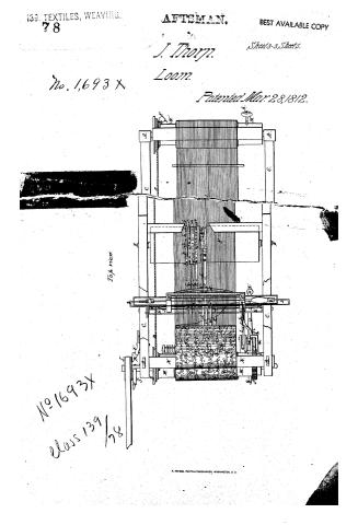
John Thorpe's Patent Drawing for a Hand and Water Loom

National Archives, Restored Patent Drawings (Record Group 241) · Full-size scan at the National Archives · Catalog record
Show the text on the drawing Hide (466 words)
Words on the drawing as machine-read by the National Archives; not checked. Useful mainly for searching.
Vol: 3 page 103. / 1693X / ON. / JOHN THORP / upright posts. / B,B, two front girts B',B', two back girts / HAND oWAHK LOOM / C,C, two side girts / Patented March 28th 1812. / D, tathe / E, E, Ends of the treaddle wheel shaft devated / F, treadde wheel. A, channal a,a,a,a, cogs- / LA / ДДЛ / H, an Elastic piece fastened to the lather / ISSN / I, hook that operates the treaddle wheel. / J,J,J,J, chains, with screws. b,b,b, gc for mornigthe troaddles / K,K, K,K, treaddles... C, block for them to restin / I,, hook or catch that prevents the action of the wheel F) / d, notch extending to the pins or cogs(a.a.) on wheel (F) / e, arm proprop which extends to just under the treaddes / side view / end view / to the cogs (a.a.) / MI, cloth beam. yarn beam / N, breast beam / f, ratchet / g. block with two mortises(hh) / i, hand or feeder / j, a piece to which the lower end of hand is connected / by the pin (k) / l, regulating COVER m, pin in lower end of lever / for liberating the hand orfeeder from the ratchet. / n. Screw for moving the upper end of lever (l) / 0, string / Eig the shuttle viberator / P1 plate of metal with its ends bent, y swing on pivots (a) / ", rod or staple, / S, arm confined to the shuttle drivers (t plat(P.) / и, slider, with mortise (v) tine end / W, pliant piece, to which the slider (и is d (shown 111. Fig: / x notches in rod (r) for the slider (u)to on the in, to throw the shattle- (Eiget) / ,,,, conductors of the shuttle drivers which are connected to the rod (z.) which slides in groove (a') in bettom of lathe(b') / 4, arms with screws s weights for staining the webb / view of Lathe / Top view. / Front / NI / Fig.2. 2. / shuttle / viberator / on a large scale. / B, whurr with creases rchannels / D, a line, with weight in lower l'oop (E.) / F, pully - G, friction lever- with weight(x) / Patent Office January 1846 / .4, crank for viberating the loom by water / August A. You Pehmide Del, / power connected by a perce (d') to the clastic priced" / de under the direction of the Commifiemer / I, 100sa pulley with pin (s') which strike the end of the arm (v') / Patents in conformity with the act of 3 of March 1837 / t', lever hung by its middle for stopping the loom with a three square piece(p") / q', knee for stopping the loom when the shuttle lodges in the webb / 2, arms of knees, extending into the boxz- 3, rod which connects the two knees / 4, arm which strikes the lever (t') to stope the Coom / Edmund Durke / Commiprioner of Patinty
USPTO scan
The patent as scanned by the USPTO
-
 Page 1
-
 Page 2
-
 Page 3
-
 Page 4
-
 Page 5
-
 Page 6
-
 Page 7


U.S. Patent and Trademark Office · Google Patents
Show the transcription Hide (1,653 words)
Machine transcription (LightOnOCR) of the pages as scanned by the USPTO, most of them the handwritten copies made when the records were restored after the 1836 fire. Not checked; it can misread handwriting, so compare it with the scan.
Page 1.
139. TEXTILES, WEAVING, 78
TERRIT. BEST AVAILABLE COPY
Draftsman
Sheet 1-3 Sheets.
J. Thorn.
No. 1693 X Loom.
Patented Mar. 28, 1812.
view of Lath
Fig. 2.
Fig. 1.
End view.
Page 2.
39. TEXTILES, WEAVING.
78
RAFTSMAN.
BEST AVAILABLE COPY
Sheet 2-3 Sheets.
No. 1693 X J. Thorn.
Loom.
Patented Mar. 28, 1812.
Side view.
Page 3.
139. TEXTILES, WEAVING.
78
ARTISMAN.
BEST AVAILABLE COPY
J. Thorp.
Sheet 3-3 Sheets.
No. 1,693 X
Loom.
Patented Mar. 28, 1812.
Top view
No. 1693X
Class 139/78
H. PETERS, PHOTO-LITHOGRAPHER, WASHINGTON, D.C.
Page 4.
1693X 163
John Thorp Letters Patent Dated March 28th 1812.
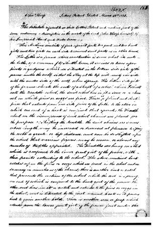
The Schedule referred to in these Letters Patent and making part of the same containing a description in the words of the said John Thorp himself of his Improved Hand and Water Loom —
This Machine consists of four upright posts, two front and two back girts and two girts on each side connected said posts as in other looms. The Lattice is a frame whose construction is some what like unto the lattice, of a common fly shuttle loom, it revolves or turns upon pivots or quodgows which are situated in the bottom side girts of the frame under the web, so that the stay at the top will nearly coincide with the under side of the web when sprung. The bottom side girts of the frame elevate the ends of a shaft of a wheel which I shall call the treadle wheel, the said wheel has in it a race or a channel in which pins or cogs are fixed. There is a plain and slotted piece that extends from one side piece of the Lattice to the other in which one end of a hook is confined that operates the Treadle wheel on the circumference of said wheel chains are screws whose length may be increased or decreased at pleasure tipping the web a greater or less distance, and can be so shifted upon the wheel that various figures may be woven, or almost any number of treadles operated. The Treadles are hung in a block which is confined to the lower front girt of the frame, with their pivots extending to the wheel. The above mentioned back catches rest on the pins or cogs which are fixed in the wheel and are so many in number as of the chains; there is another hook or catch that prevents the motion of the wheel while the web is sprung, one end of which is confined to the back girt of the frame the other end has in it a notch and extends to the pins or cogs in the wheel, and is liberated by the first named hook as it passes back to gain another hold. There is another arm or prop which extends from the lower front girt of the frame just under the
Page 5.
1693X
translates to the pins or pegs in the wheel to prevent the reaction of it. The cloth beam is hung in the two front parts of the frame a little below the breast beam, and has upon one end of it a ratchet. There is a block which extends from the front post directly under the ratchet, in whose center and a few inches, through one of which passes a band or feeder, whose upper end extends to the teeth of the ratchet, and its lower end being by a pivot in a piece that projects from the side piece of the lathe, and nearly on a level with the pivot on which the lathe swings, and a proper distance from it, to give a motion sufficient to take up the cloth. There is in the other mortice a lever which I shall call a regulating lever being on its middle for the purpose of regulating the taking up of the cloth; the pin or being fixed to take up the cloth too fast is liberated by a pin in the lower arm of the lever in consequence of its upper arm being moved by a screw in the side piece of the lathe when the cloth is beat beyond its limited position the upper arm of this lever is made fast to the lathe by a string by which it is returned to the lathe, passes back and letting the feeder call on the ratchet after it has been liberated.
That which throws the shuttle I shall call the shuttle vibrator it is affixed under the cloth in or near the breast beam swinging or turning upon the pivot or gudgeons and is constructed with a plate of metal in whose middle is a slot or mortice extending from one end past its pivot or gudgeons and is constructed with a plate of metal in whose middle is a slot or a mortice extending from one end past its pivot or gudgeons to the other, or its ends bent in which a rod or staple is confined. There is confined to the said plate one end of an arm, the other end of which extends under the bottom of the lathe to its centre of motion and is then fastened to the shuttle drivers, or a rod on which they are confined. There is another rod or a piece of metal which I shall call the slider at one end of which is a mortice or hook calculated to slide or traverse on the aforesaid rod or staple, at or near each end of the said rod or staple is a notch on which the slider catches to throw the shuttle, the other end of the said slider is confined to a pin under the
Page 6.
bottom of the lathe. The said piece to which the said slider is confined is plough and clastic so as to render the first impulse not too abrupt on the shuttle. The counterweights of the shuttle driver are rods whose upper surfaces just clear the under side of the shuttle, the said drivers are connected by a rod which slides in a channel that is cut in the bottom of the lathe.
There is inserted into the cylinder or cylinders that correspond to the harness one or more arms; the said arms are screws on whose outer ends are wheels to assist in springing the web, nor to strain the web and keep that round amount of the cloth beam. There is a line that passes round one end of the yarn beam, which has upon it a long wheel, whose arms or channels begin at the bottom of the beam and increase in circumference until they arrive at the top of the intended rolls of cloth, the lower loop of the said line contains a weight which hangs upon a pulley sufficient to strain the web, the said line is shifted from one of the said channels to the other as the cloth fills up the beam.
To support against the blow of the lathe there is a lever which I shall call the friction lever, hinged by a pivot to the side gate of the frame whose short arm presses against the yarn beam, the other arm of which corresponds a weight and extends beyond the pivot of the lathe and directly under the piece in which the beater is hung, the said piece is one for the purpose of pressing down the long arm of the lever causing a greater friction upon the beam when the lathe feels the cloth beyond its limited position when impelled by water the lathe is vibrated by a crank which is situated in the two front posts of the frame, and is connected to the piece in which the said hook is confined that operates the treadle wheel, there is just by which plays directly upon one end of the shaft of said crank and has in one side of it a pin or eye which strikes the end of an arm or lever which is confined to the shaft of said crank by a pivot. There is to the front post in range of the said pin an arm a lever long by its middle for the purpose of stopping the lever the lower arm of the last mentioned lever has upon it
Page 7.
a three square piece on its end bent, the bend of which is sufficient when ever it is moved to the point of the arm to cast it off the pin or cog and stop the loom. There is in each shuttle box a knee for the purpose of stopping the loom when ever the shuttle box in the web or misses the box one arm of each knee extends into the shuttle boxes and is nearly parallel with them.
There is in each shuttle box a knee for the purpose of stopping the loom when ever the shuttle lodges in the web or misses the box one arm of each knee extends into the shuttle boxes and is nearly parallel with them.
The other arm of the said knees are connected by a rod, so that when one is moved by the shuttle the other will have the same operation.
The arm of one of the said knees is kept in range of the upper arm of the lever which stops the loom by a light spring and would unavoidably strike and move it, which would liberate the arm from the pin or cog, if it was not moved in consequence of the shuttle striking the other arm of them, as it passes into the boxes. The friction of the said knees against the shuttle also prevents its revolting.
Witnesses
S. Dana Jr.
Christopher Burr
John Sharp
(Drawing) Made - N.W.P. 1846
Exh. 1196.
(Received and recorded a true copy Jan 28th 1848) (1852 wks)
About this record
- Patentee
- Jim Shaw's X-patent list
- Date
- the Name and Date index of patents, USPTO records, Jim Shaw's X-patent list
- Invention
- the Name and Date index of patents
- Listed in
- the Name and Date index of patents, USPTO records, Jim Shaw's X-patent list, S. A. Elliot's printed list of patents, Burke's List of Patents (1847)
- S. A. Elliot's printed list of patents gives the same name and date.
- Burke's 1847 Patent Office list gives the same patent.
- Residence from Burke's 1847 Patent Office list; the standard lists give none.