

Drawings and documents
USPTO scan
The patent as scanned by the USPTO
-
 Page 1
-
 Page 2
-
 Page 3
-
 Page 4
-
 Page 5


U.S. Patent and Trademark Office · Google Patents
Show the transcription Hide (1,524 words)
Machine transcription (LightOnOCR) of the pages as scanned by the USPTO, most of them the handwritten copies made when the records were restored after the 1836 fire. Not checked; it can misread handwriting, so compare it with the scan.
Page 2.
United States Patent
Patent No.: X1918
Thomas Blanchard of the City, and State of New York
Letter Patent.
The solicitor referred to in this Letter Patent and making part of the same, containing a description in the words of the said Thomas Blanchard himself of his horizontal shaving machine.
The invention of this improvement in machinery for shaving cloth, called the horizontal shaving machine consists in the constructing the moving horizontal shaver so as to have it move back and forth in the operation of cutting with two cranks on an axis, with a crank near each end, together with the other necessary parts constructed in the manner required for this machine. A proper wooden frame about three feet high and as wide as the cloth intended to be generally shaved may require, is made of good hard timber, having its bottom side framed together which receives and supports two posts which are the operating parts of the machine such as shavers, rollers, rolling bench, beams, bands, wheel shafts, slots and croft bars, are fixed. To complete this frame two croft beams are fixed on the outside of said posts about sixteen or twenty inches from each side and to the ends of these croft beams which may be three feet long or more are fixed, first the rolling beam on which the cloth to be shaved is first wound & at the other ends of said croft beams is fixed the axis containing the cranks to give motion to the shaver & croft bar is also put through said posts from side to side being at right angles and at the middle of said outside croft beams and secured on said posts with wedges, below the upper edge of this croft bar the cage of the under and stationary shaver rests, that is when shaving the cloth passes between the cage of the stationary shaver and the upper edge of this croft bar, which supports the said
Page 3.
United States Patent
Patent No.: X1918
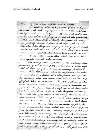
where, the edge of said crop bar must be straight.
This stationary shear is a flat plate of steel as long as the width of the cloth may require and about three inches wide having at each end a quigoon on the line of the back of said shear plate which said quigoons go into the sides of said posts so that said shear plate is nearly horizontal & its cutting edge perfectly straight & fits to the edge of the crop bar. This shear plate being thus hung by its two quigoons is easily turned up when the cloth is put in to be sheared so as to make it convenient to put the cloth between said crop bar and said shear into the rollers under them which feed in the cloth in a regular manner when shearing.
The moving shear is placed over the stationary shear consisting of two or more plates, which form a proper angle with the stationary shear as may be necessary for them to have. When the moving shear moves forward it is raised up and when it is forward it is thus pressed down against the stationary shear and moved back when it cuts the cloth off of the cloth as is wanted. The plates of the moving shear stand edgeways or their width being nearly perpendicular are fixed by means of iron straps to a crop bar, as the frame which supports or shear frame, is fixed to the horizontal post sides of the cranks that give motion to the moving shear in the manner above mentioned. These two post or crank arms extend beyond each about seventeen inches from said cranks a little beyond the shear, and the ends there are connected by joint pins to two perpendicular arms which arms are at the upper end fixed by joint pins to a bar extending across from post to post, and the moving shear being thus fixed firmly into a frame connected to said cranks, has thereby such a motion given to it as to be perfectly advantageous in shearing cloth, as said crank stays have something of a spring in their operation which prevents the cutting of the shear. The joint pins to the
Page 4.
United States Patent
Patent No.: X1918
upper ends of said arms, are fixed so as to be easily taken out and the moving shear and its frame raised up out of the way when the cloth is first put into the machine to be sheared. The axis of said cranks has at each end sockets which serve in the mode of adjusting screws by which said cranks are kept tight and are formed of a suitable bar of iron to bend near its ends as to form two cranks on the same side of the bar of iron, on one end of this axis a wooden wheel is fixed for the bands by which it is put in motion. The said crank claws are connected to said cranks with proper boxes so made as to be tightened with screws & kept firm, and the crook bar to which the arm connected to said crank claws are fixed, is made to be elevated or depressed so as to bring the edges of the shears together as the same wear away.
A long brush made to revolve on an axis is placed in the frame and its gutters go into said posts of the frame of the machine & this brush is turned by a band going round a wheel on one end of the axis of said brush so as to brush the nap of the cloth up to the edge of the shears when it is sheared off. Between this revolving long brush, and the rolling beam on which the cloth is first wound is placed a flat over a crook bar of the frame, and this flat lying upon the cloth, presses it down on said crook bar so as to prevent the cloth from being drawn in to the shears in too slack a manner, at each end of this flat a weight is suspended to give a proper degree of obstruction to the motion of the cloth as the same is drawn into the machine on one end of said rolling beam, a weight is also suspended by a rope which goes round the rolling beam in manner like a band, & this is to obstruct said rolling beam turning round too easily. The axis of the band wheel which gives motion to this machine is placed over the shears and a little backward of them and the gutters run in the upper ends of said parts of the frame. The band wheel on this axis is on this axis
Page 5.
United States Patent
Patent No.: X1918
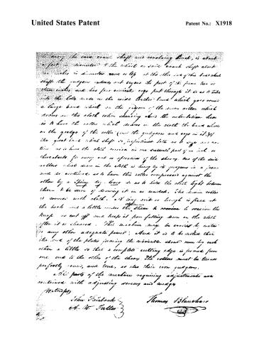
to carry the said crank shaft and revolving block, is about a foot in diameter. The wheel on said crank shaft about two inches in diameter more or less at the other end of this crankshaft shaft the propeller extends not beyond the foot of the frame two or three inches and has four conical eyes put through it so as to take into the hole made in the wide leather band which goes round a large band wheel on the periphery of the main roller which drives on the clock when chewing about the calculation here is to have the roller which draws in the cloth the band wheel on the groove of this roller (and the grooves and eyes in it) of the great band wheel shaft so proportioned both as to give and motion as is here the cloth carried in one suitable part of an inch or three eights for every cut or operation of the chewing. One of the said rollers which draw in the cloth is hung by its grooves in a frame and so continues as to have this roller compressed against the other by a spring top lever so as to hold the cloth tight between them to be sure of drawing it in as wanted. The main roller is covered with cloth, and long strip or bough is fixed at the back and a little under the chain to receive it receive the knife as cut off and keep it from falling down on the cloth after it is chewed. This machine may be carried by water or any other adequate power; also it is to be noted that the ends of the plates joining the movable sheet run by each other a little so that a complete cutting edge is formed from one end to the other of the sheet. The rollers must be turned perfectly round, and true, so also their iron grooves.
All parts of the machine requiring adjustments are contrived with adjusting screws and wedges.
Witnesses
John Fairbanks
Ed. W. Fuller
Thomas Blanchard
About this record
- Patentee
- Jim Shaw's X-patent list
- Date
- the Name and Date index of patents, USPTO records, Jim Shaw's X-patent list
- Invention
- the Name and Date index of patents
- Listed in
- the Name and Date index of patents, USPTO records, Jim Shaw's X-patent list, S. A. Elliot's printed list of patents, Burke's List of Patents (1847)
- S. A. Elliot's printed list of patents gives the same name and date.
- Burke's 1847 Patent Office list gives the same patent.