

Drawings and documents
National Archives restored drawings: drawing
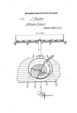
John Smelzer's Patent Drawing for a Flour Worm

National Archives, Restored Patent Drawings (Record Group 241) · Full-size scan at the National Archives · Catalog record
Show the text on the drawing Hide (116 words)
Words on the drawing as machine-read by the National Archives; not checked. Useful mainly for searching.
ILLS. / ng Mills. / ie Exhaust. / JOHN SME / Reference / 1922-X / DIVISION. / / shall or uxise / Flour Worm. / ad, geared into the running works (C) of the mill. / Patented May 6th 1813. / Page 205. Vol: 3 / crofs arms merticed together. / the upright shaft (A) in which the cross arms move up down. / TM / John Smilzer / heop - forming a lip or ledge. / near the center, for the discharge of the flour on the bott - / Cross section. / Patent Office / ( Canuary 1846. / made under the direction of the Commissioner / of Patents in Conformity with the act of / 3nd of March 1837 / August A. Von Ichmide Del: / ЕМиш / Commissioner Parke Patent
USPTO scan
The patent as scanned by the USPTO
-
 Page 1
-
 Page 2


U.S. Patent and Trademark Office · Google Patents
Show the transcription Hide (334 words)
Machine transcription (LightOnOCR) of the pages as scanned by the USPTO, most of them the handwritten copies made when the records were restored after the 1836 fire. Not checked; it can misread handwriting, so compare it with the scan.
Page 1.
NO PRINTED SPECIFICATION AVAILABLE
1922X J. Smelzer.
Millstone Exhaust.
Patented May 6, 1813.
Cross Section.

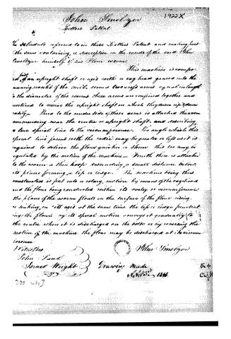
Page 2.
John Smelzer
Letters Patent
The Schenectady reference to in these Letters Patent and making just the same containing a description in the words of the said John Smelzer himself of his Flour worm.
This machine is composed of an upright shaft or axis with a cog head geared into the running parts of the mill, seems two cog arms equal in length to the diameter of the worm. These arms are confined together and notched to receive the upright shaft on which they move up & down easily. — There to the underside of these arms is attached the worm commencing near the centre or upright shaft, and describing a line spiral line to the circumference. The angle which this spiral line forms with the radius may be greater or less as it is required to deliver the flour quicker or slower. This too may be regulated by the motion of the machine. — Fourth there is attached to the worm a thin hoop descending a small distance below its plane forming a lip or ledge. The machine being thus constructed is put into a rotary motion by means of the cog head and the flour being conducted within its vortex or circumference, the plane of the worm floats on the surface of the flour rising or sinking on its axis at the same time the lip or ledge penetrating the flour by its spiral motion conveys it gradually to the centre where it is discharged on the table or by reversing the motion of the machine the flour may be discharged at its circumference.
Witnesses
John Scott
Israel Wright
John Smelzer
Drawing Made
April 22, 1846
Ex. 4
C. 4.11
300 w/h J
About this record
- Patentee
- Jim Shaw's X-patent list
- Date
- the Name and Date index of patents, USPTO records, Jim Shaw's X-patent list
- Invention
- the Name and Date index of patents
- Listed in
- the Name and Date index of patents, USPTO records, Jim Shaw's X-patent list, S. A. Elliot's printed list of patents
- S. A. Elliot's printed list of patents gives the same name and date.