

Drawings and documents
National Archives restored drawings: drawing
Thomas Bruff's Patent Drawing for a Machine for Making Shot by Pressure

National Archives, Restored Patent Drawings (Record Group 241) · Full-size scan at the National Archives · Catalog record
Show the text on the drawing Hide (205 words)
Words on the drawing as machine-read by the National Archives; not checked. Useful mainly for searching.
THOMAS RUFF / Phon / CLASSIFICATION / Machine for making Shot &C: by Pressure / 1938 / Patented June 4. 1813. Vol: 3. page 237 / Refer / 1938 / A,A, slitting rolle. grooved tengthwise, / Side view. / end view / pressing roller grooved cross-wise. / steel curve withgrouves, corresponding to those in(B) / metal frame. / top.view- / crank / AAP / F.F.F. cogs, for giving and regulating the / hrs / notion of the machine; / E' / Fig.2. / EU, in represent the Casting apparatus in different views; / Eig. 5. / caldron; / Fight / a,a,vc. iron ingots- / 000 / the furnace- / &OC1 spaces, to admit the circulation of the fire between / ingots; / gc, knobs on the bottom of the plain plates / sec: moulding at ton of ingots / vc, projections on the inside & botton of plate. / (one. selt of the) rows of cast zron arches. / flat plates of cast iron / h, iron frames for enclosing the ungots at top. / / walls of the furnace / 7, represents one of the ingots separated in order to show / the moulding on on the top and knobs at bottom of engols. / Casting apparatus. / perspective.view of ingols. / Fight / Fight Cross section / Figh. / Fig.7 / Fig. / Pateni / of Patents / 3rd of march / August A. Von Ehmidt. Deli
USPTO scan
The patent as scanned by the USPTO
-
 Page 1
-
 Page 2
-
 Page 3
-
 Page 4
-
 Page 5


U.S. Patent and Trademark Office · Google Patents
Show the transcription Hide (1,281 words)
Machine transcription (LightOnOCR) of the pages as scanned by the USPTO, most of them the handwritten copies made when the records were restored after the 1836 fire. Not checked; it can misread handwriting, so compare it with the scan.
Page 1.
1938X
I. Bruff,
Shot Machine,
Patented June 4, 1813.

Page 2.
Thomas Snuff
Sellers Patent
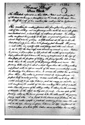
The Schedule referred to in this Letter Patent and making part of the same containing a description in the words of the said Thomas Snuff himself of his machine for making shot etc. by pressure.
This machine for making pressed shot from flat bars of lead consists of two slitting and one pressing roller with its curve all of flat, cast hardened iron, or hard brass, in a frame of metal. The slitting rollers are placed horizontally at the top, are grooved lengthwise with almost half circular grooves, a little widened at the top to let the lead pass freely from them to the pressing part beneath. The grooves in each roller are exactly alike and facing each other all round, so as to slit the bars or bars wire almost as round as wire. Between the grooves a plain space is left about the width of a small pin head, where the lead between the wires is compressed to the size of those paper for the purpose of holding the pieces together till it conducts them to the mouth of the pressing roller and curve. The pressing roller should be about a third larger than the slitting rollers, and placed with the top or mouth of the curve immediately under the dividing line between them, to receive the slitted bar as it comes from them. This roller is grooved round its circumference in perfect half circular grooves, so near each other as to bring the metal almost to an edge between, and as many in number as will comprise the width of the bar making them about a sixth wider than the grooves of the slitting rollers, to allow for the increase of diameter of the shot as they are formed. On one side of the pressing roller is the curve grooved like the roller with the grooves facing each other. It is fixed to the frame and follows the curve of the roller except a gradual widening from near the middle to the top, leaving a space between at top sufficient to receive one piece at a time of the leaden wire or slitted bar as they
Page 3.
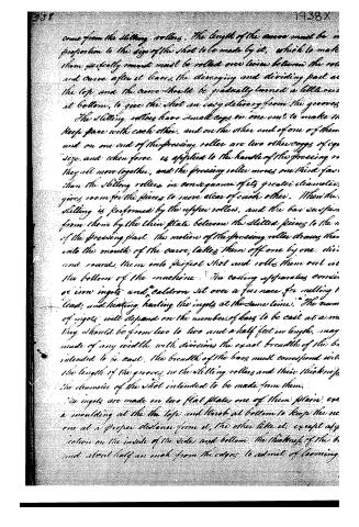
come from the slitting rollers. The length of the curve must be in proportion to the size of the shot to be made by it, which to make them perfectly round must be rolled over twice between the rollers and curve after it leaves the dividing and dividing part at the top and the curve should be gradually turned a little out at bottom, to give the shot an easy delivery from the grooves.
The slitting rollers have small cogs on one end to make them keep pace with each other, and on the other end of one of them and on one end of the pressing roller are two other cogs of equal size, and when force is applied to the handle of the pressing roller they all move together, and the pressing roller moves one third faster than the slitting rollers in consequence of its greater diameter, gives room for the pieces to move clear of each other. When the slitting is performed by the upper rollers, and the bars suspended from them by the thin plate between the slitted pieces to the end of the pressing plate. The motion of the pressing roller draws them into the mouth of the curve, takes them off one by one, divides and rounds them into perfect shot and rolls them out at the bottom of the machine.
The casting apparatus consists of iron ingots and caldron set over a furnace for melting lead, and heating heating the ingots at the same time. The number of ingots will depend on the number of bars to be cast at a time. They should be from two to two and a half feet in length, may be made of any width with divisions the exact breadth of the bars intended to be cast. The breadth of the bars must correspond with the length of the grooves in the slitting rollers and their thickness the diameter of the shot intended to be made from them.
The ingots are made in two flat plates, one of them plain, over a moulding at the top and knob at bottom to keep the one at a proper distance from it, the other like it, except at projection on the inside of the sides and bottom, the thickness of the bars and about half an inch from the edges to admit of forming.
Page 4.
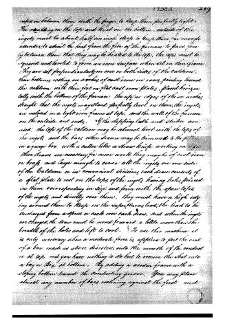
rolled in between them with the finger, to keep them perfectly tight. The moulding on the top and knot on the bottom, outside of the ingots must be about half an inch deep to keep them far enough asunder to admit the heat from the fire of the furnace to pass freely between them that they may be heated to the top, the tops must be squared and leveled to form an even surface when set in their frames. They are set perpendicularly on one or both sides of the caldron, their bottoms resting on arches of cast iron in rows, pointing towards the caldron, with their feet on flat cast iron plates, placed horizontally with the bottom of the furnace. The upper edges of these arches straight that the ingots may stand perfectly level on them, the ingots are enclosed in a light iron frame at top, and the wall of the furnace on the outside and ends. If the clefping ladle and stick are used, the top of the caldron may be almost level with the tops of the ingots and the bars when drawn may be trimmed to the pattern in a gauge box, with a cutter like a straw knife, working on a pin. When draws are necessary for nice work they may be of cast iron or brass, and large enough to cover all the ingots on one side of the caldron or in convenient divisions, each draw consists of a flat plate to rest on the tops of the ingots having holes pierced in them corresponding in size and form with the open tops of the ingots and directly over them. They must have a high edging around them to keep in the superfluous lead, the lead to be discharged from a spout or cock over each draw, and when the ingots are charged, the draw must be moved forward a little more than the breadth of the holes and left to cool. To use this machine it is only necessary when a moderate force is applied to put the end of a bar made as above described, into the mouth of the conduit or at top, and you have nothing to do but to receive the shot into a bag or box at bottom. By adding a wooden frame with a sloping bottom toward the conducting groove. You may place almost any number of bars resting against the first and
Page 5.
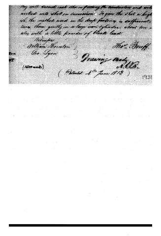
They will succeed each other in passing the conductor and will
writhe into what in succession. To give the shot a high
ish, the method used in the draft factory is sufficient;
turn them gently in a large iron cylinder, about ten
ules with a little powder of black lead
Minneapolis
William Thornton
Geo. Lyon
3 Drawing ready
A.M.B.
(Patented 4th June 1813)
1938
About this record
- Patentee
- Jim Shaw's X-patent list
- Date
- the Name and Date index of patents, USPTO records, Jim Shaw's X-patent list
- Invention
- the Name and Date index of patents
- Listed in
- the Name and Date index of patents, USPTO records, Jim Shaw's X-patent list, S. A. Elliot's printed list of patents, Burke's List of Patents (1847)
- S. A. Elliot's printed list of patents gives the same name and date.
- Burke's 1847 Patent Office list gives the same patent.