

Drawings and documents
National Archives restored drawings: drawing
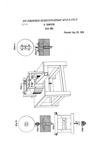
Abraham Lawyer's Patent Drawing for a Grist Mill

National Archives, Restored Patent Drawings (Record Group 241) · Full-size scan at the National Archives · Catalog record
Show the text on the drawing Hide (147 words)
Words on the drawing as machine-read by the National Archives; not checked. Useful mainly for searching.
83, MILLS. / Grinding Mills. / Patiented / Disk Action: Horizontal / 971 / #1971x / Авгикат Tawya / Vol. 3. 14.209. / CLASSIFICATION / 1971X / DIVISION. / grist Mill. / Aig.2 / Pat'd July 20th 1813 / sty.1. / figh / Giy.3. / Sig.s. / C. / Aig.b. / Referencesasa the frame posts. b. roller with wound tenons, C.C Iticks. d. crapbar / e spinale. of regulating Jerew. y. the centre or spindle bar h the weight. / i.i. bolts. sty. virw. Aiy 2 Topbino of a runner with a spindle to be / regulated by a sorew. Jij.3 fedia of Kiy.2. Jij. 4. Topoienof of a wann with the / Jij. / Putentaffie. hay / how a spinate afficed fised or the differently top. by into л Section the crap of Aig.h. bar. Sigh. the frame Jij. 7 Jection Mar under the direction afth Comm / of Satents the Can formity with act / of3 I march druy / Coumpionsol Patients
USPTO scan
The patent as scanned by the USPTO
-
 Page 1
-
 Page 2
-
 Page 3
-
 Page 4


U.S. Patent and Trademark Office · Google Patents
Show the transcription Hide (949 words)
Machine transcription (LightOnOCR) of the pages as scanned by the USPTO, most of them the handwritten copies made when the records were restored after the 1836 fire. Not checked; it can misread handwriting, so compare it with the scan.
Page 1.
NO PRINTED SPECIFICATION AVAILABLE
1971X
A. SAWYER.
Grist Mill.
Patented July 20, 1813.
Fig. 4.
Fig. 5.
Fig. 1.
Fig. 2.
Fig. 6.
Fig. 7.
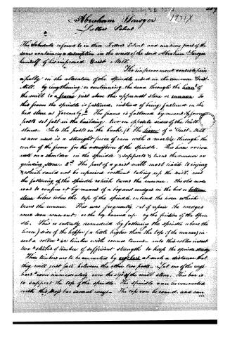
Page 2.
July 20 1813
Abraham Sawyer 1971X
Letters Patent
The above referred to in these Letters Patent and making part of the same containing a description in the words of the said Abraham Sawyer himself of his improved Grist Mill.
The improvement consists principally in the alteration of the Spindle used in the common Grist-Mill, by lengthening or continuing the same through the heart of the mill to a frame just above the uppermost stone or runner. To this frame the Spindle is fastened, instead of being fastened on the last stone as formerly. The frame is fastened by means of four posts set fast in the building, two on opposite sides of the mill stones. Into the posts on the back of the heart of a Grist Mill as now used is a straight piece of iron with a mortise through the centre of the frame for the admission of the Spindle. This heart or iron rests on a shoulder in the Spindle & supports & turns the common or grinding stone. The part of a grist mill most liable to injury & which could not be repaired without taking up the mill, was the fastening of the Spindle which turns the runner. The old mode was to confine it by means of a boy and wedges in the last or bottom stone below where the top of the Spindle entered the horn which turns the runner. This was frequently out of repair. The wedges were soon worn out; or the boy burned up by the friction of the Spindle. This is entirely remedied by fastening the Spindle above the horn) side of the hopper (a little higher than the top of the runner) insert a roller or timber with round tenons into this roller insert two sticks of timber of sufficient strength to keep the Spindle steady. These timbers are to be connected by eye bars at such a distance that they will just fall between the other two parts. Let one of the eye bars come immediately over the eye of the mill stone. This bar is to support the top of the Spindle. The Spindle can be connected with this eye bar several ways. The top can be round, and one
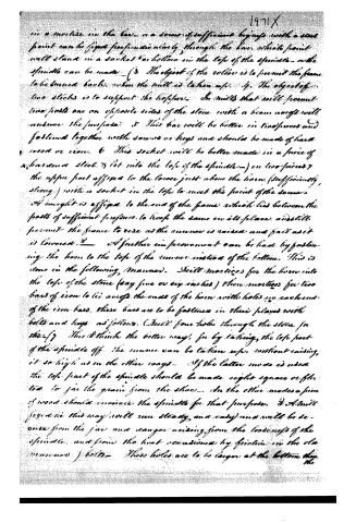
Page 3.
1971X
in a mortise in the bar, or a screw of sufficient length with a steel point can be fixed perpendicularly through the bar, which point will stand in a socket or hollow in the top of the spindle, or the spindle can be made. (3) The object of the roller is to permit the frame to be turned back, when the mill is taken up. (4) The object of two sticks is to support the hopper. In mills that will permit two posts one on opposite sides of the stone with a beam across will answer the purpose. (5) This bar will be better in two pieces and fastened together with screws or keys and should be made of hard wood or iron. (6) This socket will be better made in a piece of shearance steel, (7) let into the top of the spindle—) on two pieces (8) the upper part affixed to the lower just above the horn. (Sufficiently strong) with a socket in the top to meet the point of the screw. (9) weight is affixed to the end of the frame which lies between the posts of sufficient pressure to keep the same in its plane, and still permit the frame to rise as the anvil is raised and fall as it is lowered. (10) A further improvement can be had by fastening the horn to the top of the anvil instead of the bottom. This is done in the following manner. Drill mortises for the horn into the top of the stone (say five or six inches) then mortises for two bars of iron to lie across the ends of the horn with holes in each end of the iron bars. These bars are to be fastened in their places with bolts and keys as follows. (Drill four holes through the stone for the—) (11) This I think the better way, for by taking the top part of the spindle off, the anvil can be taken up, without raising it so high as in the other ways. If the latter mode is used the top part of the spindle should be made eight square or fluted to give the grain from the shoe. In the other modes a piece of wood should encircle the spindle for that purpose. (12) A mill fixed in this way will run steady and easy and will be secure from the jar and danger arising from the looseness of the spindle, and from the heat occasioned by friction in the old manner.) (13) These holes are to be larger at the bottom than the
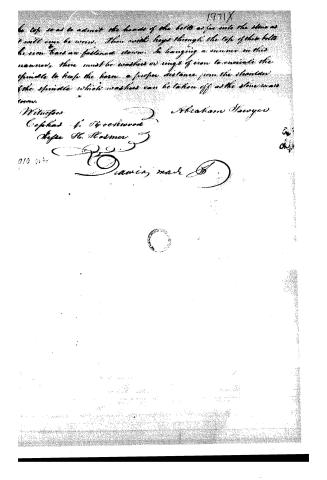
Page 4.
1971X
be top so as to admit the heads of the belts as far into the stone as it will ever be worn. Then with keys through the top of this belt the iron bars are fastened down. In hanging a runner in this manner, there must be washers or rings of iron to insulate the spindle to keep the horn a proper distance from the shoulder of the spindle which washers can be taken off as the stone wears down.
Witnesses
Cephas F. Spotswood
Joseph H. Hosmer
Abraham Sawyer
010 014
Diamin, mark D
in
ok.1
About this record
- Patentee
- Jim Shaw's X-patent list
- Date
- the Name and Date index of patents, USPTO records, Jim Shaw's X-patent list
- Invention
- the Name and Date index of patents
- Listed in
- the Name and Date index of patents, USPTO records, Jim Shaw's X-patent list, S. A. Elliot's printed list of patents, Burke's List of Patents (1847)
- S. A. Elliot's printed list of patents gives the same name and date.
- Burke's 1847 Patent Office list gives the same patent.