

Drawings and documents
National Archives restored drawings: drawing
Daniel Pettibone's Drawing for Improvements in Boring Musket, Pistol, and Rifle Barrels

National Archives, Restored Patent Drawings (Record Group 241) · Full-size scan at the National Archives · Catalog record
Show the text on the drawing Hide (343 words)
Words on the drawing as machine-read by the National Archives; not checked. Useful mainly for searching.
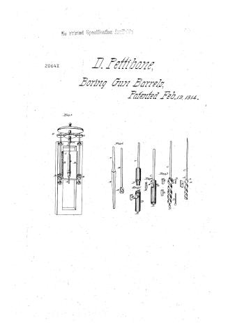
86, / WORKING, / Gun Barrels. / you / Metallurgy / Dan! Pellibone's / CLASSITICATION/ / 2064 x / Impt in boring musket-, pistol-8 rifle- barrels. / DIVISION / No.1. / DO / Patented. 12th Feb: 1814. X / No.6. / No.4 / No.3 / And / Class / 00 / No.5. / E's / References. / No. 1. AA, The bit and shank of the augur B, The barrel to be bored is fastened to the Carriage C.C, The carriage- DD, Endlefe screws. / E E, Rack of cogs to move the carriage F, Socket of the trundle headthat moves the augur.- GGG. bog wheel that gives motion to / the endleps screws, which force the barrel against the cutters of the angur at A H, a small screw to hold the shank of the anger fast / in the socket E. No. 2 is the screw augur with on without moveable points or cutters A.A, butters or points B, a piece of / stud to put into the augur to form cutters or points at pleasure C, The shank D, A feat spot in front of the cutter.- / N.3. The solid bolt or pin of steel turned in a lathe I spiral grooved cut with a file or machine. In this the moveable cutters constitute / the improvement AA, Places to apply the cutters. B, The cutters.- C, The shank D, The screws to fusten the cutters. / No is a hollow cylinder angur. A, The entrance of the chips. BB, The cutters C, The shank D D, screws to hold the cuts / ters E, The outlet of the chips on borings.- No. 5, A cylinder angur.- A, The entrance of the chips. BB. The cutters.- / C, The shank D, A small screw to hold the cutters in their places F, A screw that enters at G. No. Augurs for, / merly used at springfield, fo. A,B, The nut bit 0,A, The square bit on augur. These angural are now laid afride A long / square bit is used only for smooth horing - / (note made from certified Copy, dated: 19 March 1814.)
USPTO scan
The patent as scanned by the USPTO
-
 Page 1
-
 Page 2
-
 Page 3
-
 Page 4
-
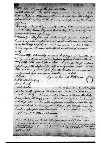 Page 5


U.S. Patent and Trademark Office · Google Patents
Show the transcription Hide (1,361 words)
Machine transcription (LightOnOCR) of the pages as scanned by the USPTO, most of them the handwritten copies made when the records were restored after the 1836 fire. Not checked; it can misread handwriting, so compare it with the scan.
Page 1.
No Printed Specification Available
2064X
D. Pettibone,
Boring Gun Barrels,
Patented Feb. 12, 1814.
Fig. 1.
Fig. 6.
Fig. 3.
Fig. 4.
Fig. 5.
Page 2.
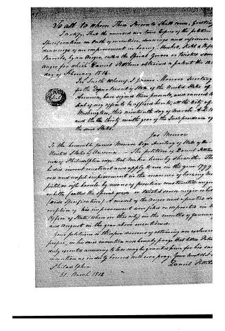
To all to whom These Presents shall come, Greeting.
I certify, That the annexed are true copies of the petition, Specification on oath of invention, drawings and references & drawings of an improvement in boring - Musket, Pistol & Rifle Barrels, by an Anger, called the Special Groove or twisted screw Anger for which Daniel Attitono obtained a patent the 12th day of February 1814.
In Suite Whereof, I James Monroe Secretary for the Department of State of the United States of America, have signed these presents, and caused the Seal of my office to be affixed here to, at the City of Washington, this nineteenth day of March A.D. 1812 and the thirty ninth year of the Independence of the said States.
Jas Monroe
To the honorable James Monroe Esq Secretary of State of the United States of America. — The petition of Daniel Attitono of Philadelphia esq - to be heard humbly sheweth — That he did invent construct and apply to use in the year 1799 new and useful improvement in the manner of boring the pistol or rifle barrels by means of peculiar constructed anger or litty (called the special groove or twisted screw anger or litty [vide Specification]) A model of the Anger and a painting description of his improvement were filed or deposited in the Office of State (when in this city) in the months of January and August in the year above mentioned.
Your petition is therefore desirous of obtaining an exclusive proper in his said invention and humbly prays that letters Patent duly executed according to law may be granted him for his said invention as in duty bound will ever pray. Your most obdt
Philadelphia
31. March 1812
Daniel Attitono
Page 3.
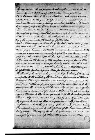
Specification. To all persons to whom these presents shall come, Samuel Potters, of London, in the county of Middlesex, Gent. Know ye, That I Samuel Potters, did invent and apply to use in the year 1799, a new and useful improvement in the manner of boring musket, pistol, or rifle barrels by an auger (called the spiral gauge or twisted screw auger). The invention of the spiral gauge or twisted screw auger for the purpose of boring musket, pistol, or rifle barrels, consists in the manner of making it; or the particular form or construction of the same; or also the mode of application.
First—These augers are made of the best cast or other good steel, welded to a handle or shank of good iron or steel. Then they are forged, hammered & twisted in a similar manner to the common screw augers, used by carpenters for boring wood, excepting the plate is left thicker before it is twisted. The difference in the form of this improved auger from the common screw auger and for boring wood, are that the points or cutters are next to the shank; and that the auger is life twisted for boring iron than for boring wood.
The shank of the auger is long enough to put through the barrel and fasten to the socket of the machine that moves or turns the auger. The auger revolves about once per second and the points or cutters are pressed against the iron that is to be bored from the inside of the barrel: By the force or application of one or more endless screws that revolve in a rack of cogges attached to the carriage on which the barrel or portion thereof is placed. These endless screws revolve very slowly so as to give time for the augers to cut all that is required.—My further improvement is the placing of the barrels perpendicularly. The improved auger can be well applied if the barrels are placed horizontally. The size of the shank of the augers are about one eight of an inch less than the screw or cutters.
Page 4.
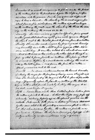
I consider it of much consequence to file or make the point of the cutters flat in the front so as to give the chips a proper direction into the grooves. I make use of several different sizes to have a barrel:—the shank of the second auger, for about four or five inches from the cutters is just as large as the cutters of the first—and the shank of the third the same size as the cutters of the second &c. &c. &c.
Secondly—For convenience of repairs I put a piece of cast or other good steel about one eight of an inch square through the shank next to the twisted part to form points or cutters.
Thirdly I have also made augers by forging and turning very smoothly in a lathe a bolt or pin of good steel—six or seven inches long—It was then welded to a shank at one end—and within one or two inches of the other I put through a piece of steel to form points or cutters. This piece of steel is secured in its place by a small screw entering the end or side of the bolt or pin.—and from the points or cutters.—Spiral grooves are cut to the end.
Fourth—In some instances I cause the barrel to revolve instead of the auger for the purpose of boring more straight and true. The twisted part of the auger is best to be from six inches long. I frequently repair the points or cutters of the twisted augers with a steel punch or set, by heating the auger to a red heat—and temper it again.
Fifth—Sometimes I make these bolt or pins hollow from the cutters or points to the end.—so that the chips may pass off internally, instead of passing off in the spiral grooves on the outside. I also make bolt/pins, or hollow cylinders that come together somewhat like the points of a common flute or clarinet that when screwed together—the cutters or points are fastened in its place—the chips or barings pass off internally or externally as circumstances may require.
Page 5.
2064X 32
The Advantages of the five Articles.
Article Firstly. The same auger is more easily made & kept in repair than any other; and will bore the straightest without injury to the barrel; and of an excellent size all the.
Secondly. By putting movable cutters to the same auger as to the other kinds, they will last a long time, as only the cutter will need repairing.
Thirdly. The placing the barrels perpendicular to be bored is a great improvement as it will save much room in a building or factory. And one man can bore two or three augers at once. Also the chips will drop out conveniently.
Fourthly. The making some such of cogs is a matter of consequence to give a regular pressure against the cutters.
Fifthly. The making of hollow augers for the purpose of passing of the chips internally is very convenient. But there is none of the simplicity of the twisted screw and so easily made by a common workman & tools.
Witness
Signed Daniel Pittsboro
J. P. D. Muhlenberg
Jas. J. Knech
Jacob Baker
City and County of Philadelphia
I personally appeared the above named Daniel Pittsboro and being duly cautioned and solemnly oath on the holy Evangelist of Almighty God: That he really believes himself to be the first inventor of the improved method of making augers or bits for boring, mortar, pistol, & Rifle barrels, as above specified and described. And that he is a citizen of the united States of America.
Signed Daniel Pittsboro
Sworn the 31 day of March 1818 before me Jacob Baker (clerk)
I examined on the books. He then swore to me that he had seen your book and stick standing perpendicular by the auger's diameter, nearly nine years ago, 1809.
Daniel Pittsboro
(1452 words)
Deposition of Jacob Baker
DATAMP: illustration
Illustrations from DATAMP


DATAMP (Directory of American Tool and Machinery Patents), via the Internet Archive · Archived DATAMP page
About this record
- Patentee
- DATAMP
- Date
- the Name and Date index of patents, DATAMP, USPTO records
- Invention
- DATAMP
- Listed in
- the Name and Date index of patents, DATAMP, USPTO records, Jim Shaw's X-patent list, S. A. Elliot's printed list of patents, Burke's List of Patents (1847)
- S. A. Elliot's printed list of patents gives the same name and date.
- Burke's 1847 Patent Office list gives the same patent.