

Drawings and documents
National Archives restored drawings: drawing
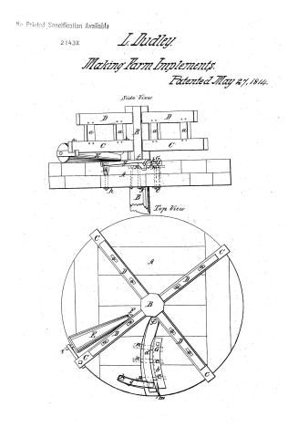
Luther Dudley's Patent Drawing for a the Manufacture of Sythes

National Archives, Restored Patent Drawings (Record Group 241) · Full-size scan at the National Archives · Catalog record
Show the text on the drawing Hide (179 words)
Words on the drawing as machine-read by the National Archives; not checked. Useful mainly for searching.
2. / 81. METAL WORKING, / this CLASSIFICATION / 6. TOOLS. / Farm Implements. / LUTHER DUDLEY. / 2143-X / DIVISION / Machine for the / Manufacture of shythes. / Reference. / Patented May 27 1814 Voli 3 page 321. / Top view. / latform of hard timber / rpendicular shaft / side view / er arms of timber / D.D, / ms; & braces. a,a,se) / E, conical cast iron roller / P,P, gudgrons of cast iron reller. / G, curveliniar griping vices / b. right hand jaw permanentely bolted. / << / e,c, the bells / d, moving jaw with juint belt(f,) / Ge / g. strong iron latch, with u strong / spring (h,) for its gudgeon / 2, curved angle which acts against she / outer end(j) of moving jaw - / k, space for receiving the sythe, edge upwards / G. / between the jaws (cl,b,) / OF / m, spring, for moving the jaw( d back. / (izz / r n,a, iron cross pieces with belts - / Patent Office / Febz 28th 1846 / Augus Schmidt Del: / made under the direction of the Commissioner / Patents in conformity with the act 3rd of Mac / Атими De / Commision
USPTO scan
The patent as scanned by the USPTO
-
 Page 1
-
 Page 2
-
 Page 3
-
 Page 4


U.S. Patent and Trademark Office · Google Patents
Show the transcription Hide (1,418 words)
Machine transcription (LightOnOCR) of the pages as scanned by the USPTO, most of them the handwritten copies made when the records were restored after the 1836 fire. Not checked; it can misread handwriting, so compare it with the scan.
Page 1.
No Printed Specification Available
2143X
L. Dudley
Making Farm Implements.
Patented May 27, 1844.
Side View

Top View

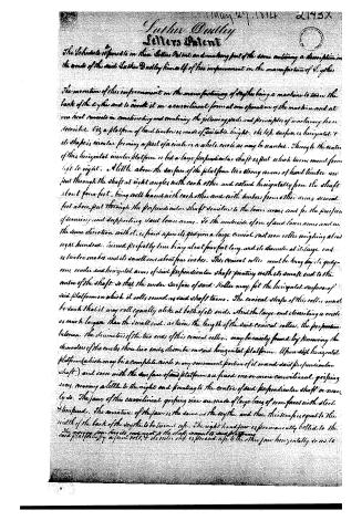
Page 2.
May 27, 1814 2175X
Luther Dudley
Letters Patent
The Schedule referred to in these Letters Patent and making part of the same containing a description in the words of the said Luther Dudley himself of his improvement in the manufacture of Cylinders.
The invention of this improvement on the manufacture of Cylinders being a machine to turn the back of the Cylinder and to crook it on a curvilinear form at one operation of the machine and at one time consists in constructing and combining the following parts and principles of machinery here described. viz a platform of hard timber is made of suitable height. Its top surface is horizontal & its shape is circular forming a part of a circle or a whole circle as may be wanted. Through the center of this horizontal circular platform is fed a large perpendicular shaft or post which turns round from left to right. A little above the surface of the platform two strong arms of hard timber are put through the shaft at right angles with each other and extend horizontally from the shaft about four feet, being well braced with each other and with timbers from other arms second feet above, put through the perpendicular shaft similar to the lower arms, and for the purpose of securing and supporting said lower arms. To the underside of one of said lower arms and in the same direction with it, is fixed upon its gudgeon a large conical cast iron roller weighing about eight hundred, turned perfectly true, being about four feet long, and its diameter at its large end is twelve inches and its small one about four inches. This conical roller must be hung by its gudgeons under said horizontal arms of said perpendicular shaft pointing with its small end to the center of the shaft so that the under surface of said roller may fit the horizontal surface of said platform on which it rolls round as said shaft turns. The conical shape of this roller must be such that it may roll equally alike at both of its ends. And the large end describing a circle as much larger than the small end, as twice the length of the said conical roller, the proportion between the diameters of the two ends of this conical roller, may be easily found by knowing the diameters of the circles those two ends describe on said horizontal platform. Upon said horizontal platform (which may be a complete circle or any convenient portion of it round said perpendicular shaft) and even with the surface of said platform are fixed one or more curvilinear grooving irons, curving a little to the right and pointing to the center of said perpendicular shaft or nearly so. The jaws of this curvilinear grooving iron are made of large bars of iron fastened with steel & hinges. The curvature of the jaws is the same as the cylinder and their thickness is equal to the width of the back of the cylinder to be turned up. The right hand jaw is permanently bolted to the said platform by a joint bolt, & its other end is pressed up to the other jaw horizontally so as to
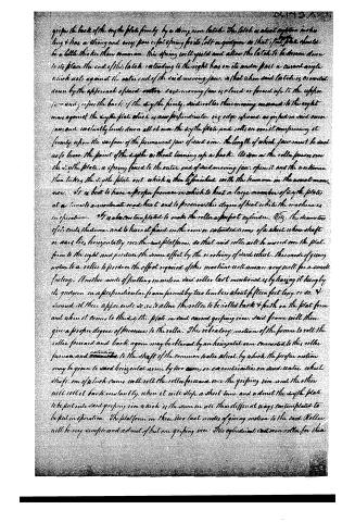
Page 3.
grip the back of the sythe plate firmly, by a strong iron latch. This latch is about eighteen inches long & has a strong and easy power of spring fitted in a guttiron so that if the plate should be a little thicker than common, this spring will yield and allow the latch to be drawn down to its place. The end of this latch extending to the right has on its under part a curved angle which acts against the outer end of the said moving jaw, so that when said latch is so curved down by the approach of said roller, said moving jaw is closed or forced up to the sythe jaw and grips the back of the sythe firmly, said roller then moving onward to the right comes against the sythe plate which is now perpendicular in edge upward as gripped in said jaws, and instantly bends down all at once the sythe plate, and rolls on over it compressing it firmly upon the surface of the permanent jaw of said vice. The length of which jaw must be such as to leave the point of the sythe without turning up a hook. As soon as the roller passes over the sythe plate, a spring fixed to the outer end of said moving jaw, opens it and the workman then takes the sythe plate out which is then to finished with the hammer in the usual manner. It is best to have a proper furnace in which to heat a large number of sythe plates at a time to an moderate red heat, and to preserve this degree of heat while the machine is in operation. It is also contemplated to make the roller a perfect cylinder. Viz. the diameter of its ends the same, and to have it fixed in the rim or extended arms of a wheel whose shaft or axis lies horizontally over the said platform, so that said roller will be moved over the platform to the right and produce the same effect by the revolving of said wheel. This mode of giving motion to a roller to produce the effect required of this machine will answer very well for a small factory. Another mode of putting in motion said roller last mentioned is by having it hung by its guttiron in a perpendicular frame formed by two timbers about fifteen feet long, or so, & divided at their upper ends so as to allow the roller to be rolled back & forth on the platform and when it comes to the sythe plate in said curved gripping vice, said frame will then give a proper degree of pressure to the roller. This vibratory motion of the frame to roll the roller forward and back again may be obtained by an horizontal arm connected to this roller furnace and extending to the shaft of the common water wheel, by which the proper motion may be given to said horizontal arm, by two arms or eccentricities on said water wheel shaft, one of which arms will roll the roller forward over the gripping vice and the other will roll it back instantly, where it will stop a short time and admit the sythe plate to be put into said gripping vice which is the same in all these different ways contemplated to be put in operation. The platform in these two last modes of giving motion to the said roller will be very simple and admit of but one gripping vice. This cylindrical common roller for these
Page 4.
the last motion of lifting up it for the first time afterwards may be about eight inches in diameter. The use of the machine saves much time in making it. It is to be noted that the moving jaw of the gripping vice has two or more of pieces of iron bolted on the under side and let into the platform as well under the permanent jaw as back side of said moving jaw, so as to prevent said moving jaw from rising up or from being bent up above the horizontal surface of the platform, and when the said plate is put into said gripping vice, it rises upwards its back rests upon said coap pieces as the usage of the height of the back of the vice which must be straight when put into said vice to have its back turned. The permanent jaw of the gripping vice must be no longer than the back of the same that is to be turned, and for vices of different lengths it is best to have permanent jaws also of different lengths accordingly to be put in and taken out. I all to fit the said moving jaw especially in machines that have but one gripping vice.
Witnesses
John Fairbanks
Hose & Morse.
(1368 or 1369)
Author Dudley
Drawing made
A. H. Voss

About this record
- Patentee
- DATAMP
- Date
- the Name and Date index of patents, DATAMP, USPTO records
- Invention
- DATAMP
- Listed in
- the Name and Date index of patents, DATAMP, USPTO records, Jim Shaw's X-patent list, S. A. Elliot's printed list of patents
- S. A. Elliot's printed list of patents gives the same name and date.