

Drawings and documents
National Archives restored drawings: drawing
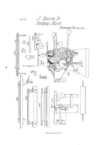
John Bazin, Junior's Patent Drawing for a Stocking Loom


National Archives, Restored Patent Drawings (Record Group 241) · Full-size scan at the National Archives · Catalog record
Show the text on the drawing Hide (308 words)
Words on the drawing as machine-read by the National Archives; not checked. Useful mainly for searching.
Sheet 1. NETTING, / Straight, Straigh 08. / CLASSIFICATION / 2211- X / References / DIVISION / vol Britd 317 Pats. / to the Drawing of / John Bazin Junrs / Stocking Loom / Reepage / The parts are figured in the order ad they are described in / the sepecification. / Fig / The stocking loom in perspective / 2 A section the outline shewing the side plates- the shaded parts / the needle, tickler and sinker and an end view of the different bars / in the drawing. / 3. Needle slace bar the piece marked c being one of the slaie pieces / cast inflead.- / 4. Ticklar bar the piece marked A one of the slaie pieces / a ticklar cast inflead.- / 5. Sinker slace bar. B one of its slace pieces.- / 6. Needle and needle plate / % A sinker- (its operation is the same in principle as the jack / of the common staching loom and should have been so called) / 8. / The ticklar cast in flead.- / A section of fig 1. A is the cam on the main shaft to lift / the lever and weight P B is the ratchet wheel on the cylinder on / which the stocking winds. / 10 The carrier the carrier bar and carriers can be seen an top of / the perspective fig 1. / 11. Needle lifter bar- and catch bar an top / 12.- The roller and frame which works the sinkers (an jacks) it / answers to what is called the slur in the common stacking frow / 13. Shuttle frame.- / (Loose sheet accompanying the Patent returned / for record.-)
Sheet 2. 05 / All / athis / 2211X / 2211 / John Bazin Jun / Stocking Loom I / Pat: 23 Oct: 1814. / Fig4. / Feig ". / stail / Figle / has / Feig3. / syr!! / Fig 13 / for / and / need slace / operation his I / the / Fig 9 / whyou / Fig 5 / Fig12 / Fig 10 / 100mg / tables / has days much / are / >> / PL / me belief and / smoker / operated / pass / mudles / meadle / Fig2 / for / 4pm famfall / Frig
USPTO scan
The patent as scanned by the USPTO
-
 Page 1
-
 Page 2
-
 Page 3
-
 Page 4
-
 Page 5
-
 Page 6
-
 Page 7
-
 Page 8
-
 Page 9
-
 Page 10
-
 Page 11


U.S. Patent and Trademark Office · Google Patents
Show the transcription Hide (3,154 words)
Machine transcription (LightOnOCR) of the pages as scanned by the USPTO, most of them the handwritten copies made when the records were restored after the 1836 fire. Not checked; it can misread handwriting, so compare it with the scan.
Page 1.
2211X
J. Bazin, Jr.
Knitting Mach.
Patented Oct. 28, 1814.

Page 2.
Oct 28, 1814
John H. Bowne, Inventor
2211X
Letters Patent
The Inventor intends to secure his Letters Patent and making proof of his invention as a description in the words of the said John Bowne from himself of his improvement in the Stocking Loom.
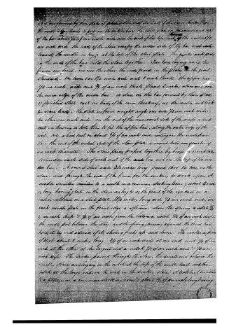
This improvement in the Stocking Loom consists of a framework containing and line as according to the following description. A bench formed by a plank of hard wood 3 feet long and 1 foot wide having 4 legs to it of a suitable height, a iron frame 23 inches wide and 12 inches high fastened on the top of the bench. The front standards of the frame 2 cast iron plates 4 inches wide laid together by 3 horizontal iron bars or pillars 22 inches long (two at the bottom and one in the middle) passed through them and fastened by a nut and screw at each end. At the top of the standards, secured on the inside, a horizontal iron bar 7 inches long and one 3 inches from the bottom, 7 inches long. The back standard a cast iron plate 1/2 in wide screwed in the bars parallel to the front standards, 4 1/2 inches from them, having on the edge towards the front a circular projection and in the back edge 3 inches from the top a notch 1/4 inch wide cut in as far as the centre. A round iron plate 21 inches long passing through the end of the top bars and fastened by a nut and screw at each end. At the top of the front standards, secured on near the edge a cast iron plate 6 inches wide projecting out 6 inches in front. On the top bars, one iron or brass plate about 2 inches wide and 4 inches long screwed on between the standards having a quarter at top and a round hole 2 inches below the top of the bar, one iron axle 1/2 inch diameter the quidions working in a brass plate screwed on the back standard over the notch projecting out at each side of the frame about 3 inches and squared. The end of the axle on the right side of the frame rounded like an inch in length. On the right side of the frame a cast iron standard 12 inches high screwed on the bench having an arm on one side 3 inches long with a hole in the end through which the end of the large axle passes. A standard 10 inches high screwed on the bench parallel to the other. One axle the quidions working
Page 3.
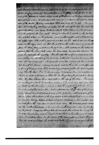
in the Standards having a pinion on the end near the frame & a toothed wheel between the two Standards. on the top of the main Standard a block to prevent the axle from being turned backwards. on the large axle a cogwheel 8 inches diameter. on the arm of the Standard a pinion on an axle between the cogwheel on the large axle and the pinion on the axle, 8 inches on the outer end of the count axle. the axle being turned by the wind, the pinion on the end turns the pinion on the arm of the Standard and the cogwheel on the large axle. the large axle makes one turn to four of the small axle. & though the frame having the ends fixed on the front Standard 2 inches from the top. 2 polished steel bars, 6 inches long, 1/4 of an inch apart one in front of the other. The front bar half the width of the boat: a space between the bars formed by thin plates of polished steel cast in lead about 2 times their thickness, put upon the back bar and joined together by iron or brass plates 3 inches long screwed on the top and back of the bar at each end; the steel plates as wide as the space between the bars, and as high as the top of the frame the lead cast on the steel plates covers the under side, back and top of the bar, leaving a perpendicular opening between each plate for the wheels to move in. through the top of the steel 1/4 of an inch from the upper edge an aperture 1/4 of an inch long across the top of the slide and 1/4 of an inch wide: at each end of the slide pieces on the bar a piece of brass or iron of the same form to prevent the slide from bending. a steel plate screwed on the outside of the front Standard at the top having a groove at the top 1/4 inch deep & a corresponding groove in the slide and 1/4 an inch wide towards the front. A Steel Bar called the tail bar laying across the frame in the grooves in the steel plates, projecting out about 1/4 of an inch at each side and turned round at the ends on the upper side of the bar at each end a piece of iron or brass 3 inches long and on the under side a perpendicular guide formed by a piece of iron bent right angles— one side screwed to the bar by 2 screws passing thru into the pieces of iron on the top. the other side of the angle about 1/4 of an inch from the Standard on each end of the bar and gives a friction roller working against the inside of the Standard. the end of the guide next again a pin screwed into the Standard, and on each end of the bar in front of the slide a spring one end pressing against the tail bar, the other end against the end of the guide.
Page 4.
A 4" slice formed by three plates of polished steel and one inch of the same thickness. One the needle slide heads is fast on the table bar. The slide plate on the anterior end of the bar about 1/2 of an inch wide and the ends of the top fork of the needle is an inch wide. The head of the slice occupy the entire width of the bar and slide towards the needle as large at the top of the slice plate. The guides and plate on the ends of the bar hold the slice together. The bars laying across the frame on frame, one over the other, the ends passed in the plate, in the front standards. The frame bar 1/2 inch wide and 1 inch thick. The upper bar 1/2 an inch wide and 3/8 of an inch thick. Plate 3 inches above and on the inner edge of the under bar. A slice on the bar formed by three plates of polished steel cast in bands of the same thickness as the needle and slide bar slide heads. The plate in form a right angle one side 1/2 an inch wide, the other one inch wide. On the end of the rearward side of the angle is a band cast in having a hole thru to fit the upper bar, along the outer edge of the wide side a band cast in about 3/8 of an inch wide resting on the under bar. The end of the widest side of the slice plate a round hole one quarter of an inch diameter. The three pieces fastened together by bolts in six plates screwed on each side of each end of the under bar and on the top of the under bar. A round steel axle 3/8 inches long passed thru the holes in the slice, and through the ends of the frame for the sinkers to work upon. A needle similar similar to a needle in a common stocking loom) about 2 inch long having 1/2 cuts in the slice as large as the front of the eye cast in a band or cold out in a steel plate 1/2 inches long and 1/2 an inch wide, in each needle plate in the front edge a spring, above the spring a notch 1/4 of an inch deep 5/8 of an inch from the bottom a notch 1/4 of an inch deep. The needle put between the slice and the spring pressing against the front bar holds it by and admits of its sliding freely up and down. The sinker a piece of steel about 8 inches long 3/8 of an inch wide at one end and 1/8 of an inch at the other at the largest end a notch 1/4 of an inch wide 5/8 an inch deep. The sinker passed through the slice, the small end between the needle slice and laying in the notch at the top of the needle head and the notch at the large end on the wide on the sinker slice. A bolt (similar to a bolt in a common stocking loom) about 3/8 of an inch long having
Page 5.
28113
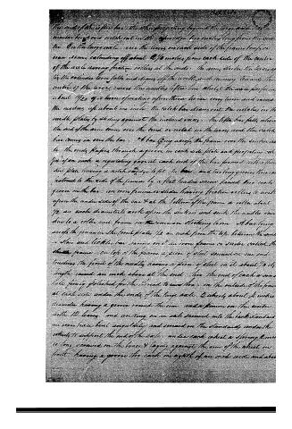
a plate along the front of the steam to the front, next in a bar and put the lower the plate on the tickler bar. The bar is little under steam the lower plates and formed to fit the drawing between. The rod that has the tickler properly above the edge and over the end of the plate towards the needle. The tickler standing above the bar makes towards and back down against the face of the needle. The point entering the plate, the top of the bar a little wider than the eye of the needle, and stepped down towards the point. The tickler held in the steam by an iron bar laying on top of them and fastened to the tickler bar by a thumb screw at each end. The holes at the end of the bar act in such a way that the bar can be taken off without drawing out the screws. On the front of the guides of the tickler bar, a piece of iron is set projecting down to insert the top bar from drawing against the screw at the top of the groove in the steel plate at the top of the standards, a notch about 1/8 of an inch deep the tickler bar when raised up is pushed into it by the spring so that the points may stand clear of the needles. A bar called the gage bar 19 inches long passed thru the steam back of the needle, leaving 1/8 of an inch space between them and the bar. On the top of the steam a bar called the stop bar to hold down the drawing pin when the needles rise up, fastened to the gage bar by a thumb screw at each end. The holes in the stop bar cut lengthwise so that it can be taken off without drawing out the screws. A spring screwed on each end of the steam bar, the end resting against the gage bar. On the side of the pinion on the large axle a solid wheel of brass, 3 inches diameter having two notches on the edge about 1/4 of an inch deep and 1/8 of the circumference of the wheel in length. A square iron axle called the lever axle, the spindles working in a brass plate screwed on the outside of the standards back of the needle steam bar, having an iron arm 4 inches long screwed on at each end resting against the gage bar, an iron arm 6 inches long screwed on the end, having at the other end resting on the edge of the wheel on the axle. The axle fastens forward the gage bar against the needles by the wheel raising the pin on the arm out of its notch, holds it against them. When they are rising up until the ticklers come down and take up the loops. The notches in the wheel then coming under the pin on the axle of the arm. The springs push back the gage bar, a spring of wood 9 inches long.
Page 6.
and 3 inches diameter account with each having an iron axle placed in the centre working below the top of the frame, on the plate on the top bars on the end of the cylinder a notched wheel inside of the frame on the large axle a solid wheel of brass or iron 4 inches diameter having a notched edge on each side of the axle 3 1/2 of an inch deep 4 1/2 inch wide at the top. The iron bar 18 inches long working on a pin at the end of the top bar near the great standards and laying between the notched wheel on the cylinder and the wheel on the large axle having a notched to catch on the teeth of the notched wheel on the cylinder, a movable weight and notches cut in the upper edge like a stick yard and a pin on the side to rest on the wheel on the large axle so that the notch in the wheel coming under the frame the lever falls and turns the cylinder: The notches in the wheel so placed that the lever falls when the lever axle has pushed forward the page bar against the needles. On the slab bar a pin is screwed on the end resting on the axle of the cylinder to prevent it from turning when the lever rises up. A movable iron bar resting at the end on the top bars of the frame, having at each end on the under and upper side a piece of brass or iron 2 1/2 inches long screwed together by 3 screws passing thru the bar. On the bar as many carriers as there are needles in the frame and so placed so that the bar being brought forward to those dies they pass between them and rest on the edge of the slab. The carriers are needles (similar to the working needles) 1 1/2 inch long cast in a solid as thick as the slab bar, having a hole through it to fit the bar on each end of the carrier bar. A chain passed over the pillar of the frame and joined to a hook at each end of the cylinder. At each side of the frame upon the outside on the large axle a solid wheel of brass or iron 4 inches diameter having 4 pins placed at equal distances on the surface 1/4 of an inch from the edge two on each side, one the wheel a pin screwed on the back standards. The iron lever or balance 18 inches long working on the pivot having an oblong hole at one end thru which the end of the lever bar passes and a brass or leather bale on the other end to counter with the lock bar, on the inside of the lever a piece of steel 3 1/2 inches long screwed on between the axle and bale. The end laying against the
Page 9.
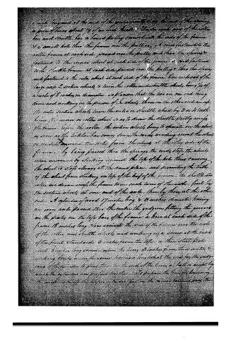
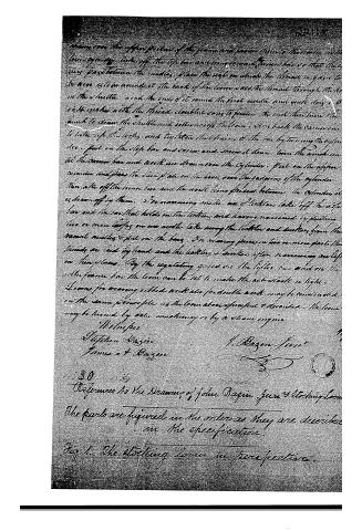
1 inch long each at the ends of the frame members on the ends of the spring, a piece of brass about 1/8 of an inch thick. The roller ends and of the roller bar and shuttle bar a bored pulley secured into the side of the frame & a small hole thru the frame on the pulleys, & each fastened to the roller frame at each side passed over the pulley and thru the spring & fastened to the inner wheel at each side of the frame & each fastened to the shuttle frame at each side passed over the pulley & thru the spring and fastened to the outer wheel at each side of the frame. One end each of the large outer & section wheels to turn the roller and shuttle wheels being 1/4 of a circle of 8 inches in diameter, so placed that the two on one end being down and working on the pinions of the wheels, those on the other end are up, the outer section wheels turn the outer or shuttle wheel by 3 or 4 teeth being the inner or roller wheel so as to draw the shuttle partly across the frame before the roller. The section wheels being to operate on the wheels as soon as the tickler bar comes down the cords winding around the wheels on one side unwind the cords from the wheels at the other side of the frame. By being passed thru the springs the cords stop the wheels when unwound by striking against the top of the hole thus causing the wheel to stop always at the same place and preventing the teeth of the wheel from striking on top of the bar of the pinion. The shuttle and roller are drawn across the frame twice each turn of the axle. First by the section wheels at one end of the axle, then by those at the other end. A cylinder of wood 17 inches long & 8 inches diameter having on one side passed thru the center the guide pins fitting the grooves on the plates on the left bars of the frame & bore at each side of the frame 18 inches long side against the side of the frame over the axle of the roller and shuttle wheels and working on a screw at the back of the front standards 4 inches from the top & then start plate about 8 inches long screw upon the bars 3 inches from their center & working freely under the screw having a long bolt at the end for the guide pins of the cylinder to pass thru on the end of the bars a bolt is caught by which the cylinders are pressed together. To prepare the frame for beginning the work take off the upper cylinder, fast on the center bar and pass the
Page 10.
30
References to the Drawing of John Bazin, Jr. & Stocking Loom
The parts are figured in the order as they are described in the specification.
Fig. 1. The Stocking Loom in perspective.
Page 11.
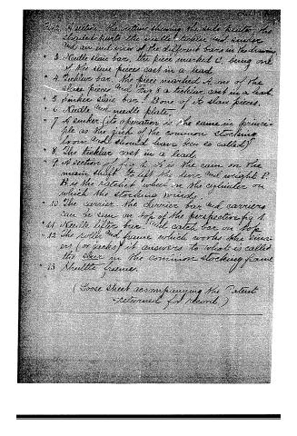
Fig. 2. A section. The section showing the slide plate, the shouldered parts, the needle, tickler, and sinker, and an end view of the different bars in the drawing.
3. Needle slide bar, the piece marked C, being one of the slide pieces cast in a lead.
4. Tickler bar. The piece marked A, one of the slide pieces and Fig. 8 a tickler cast in a lead.
5. Sinker slide bar. One of its slide pieces.
6. Needle and needle plate.
7. A sinker. (Its operation is the same in principle as the jack of the common stocking loom and should have been so called.)
8. The tickler cast in a lead.
9. A section of Fig. 1. A is the cam on the main shaft to lift the lever and weight P. B is the ratchet wheel on the cylinder on which the stockings wind.
10. The carrier. The carrier bar and carriers can be seen on top of the perspective Fig. 1.
11. Needle lifter bar and catch bar on top.
12. The roller and frame which works the carriers (or jacks) it answers to what is called the sliver in the common stocking frame.
13. Shuttle frame.
(Loose sheet accompanying the Patent returned for record.)
About this record
- Patentee
- DATAMP
- Date
- the Name and Date index of patents, DATAMP, USPTO records
- Invention
- DATAMP
- Listed in
- the Name and Date index of patents, DATAMP, USPTO records, Jim Shaw's X-patent list, S. A. Elliot's printed list of patents, Burke's List of Patents (1847)
- S. A. Elliot's printed list of patents gives the same name and date.
- Burke's 1847 Patent Office list gives the same patent.