

Drawings and documents
National Archives restored drawings: drawing
J. F. Chappius Patent Drawing for a Spinning Machine


National Archives, Restored Patent Drawings (Record Group 241) · Full-size scan at the National Archives · Catalog record
Show the text on the drawing Hide (777 words)
Words on the drawing as machine-read by the National Archives; not checked. Useful mainly for searching.
Sheet 1. 118. SPINNING / [142] Hemp Flax & Hair / VIV. 21. / 9.50 / CLASSIFICATION / 2216.4 / J.F. Chappius / DIV ISION. / Spinning Machine / Patented Nov. 8th 1814 / is / FL / SECURITY / of / TRJ / do / F' / R. / OIR / made under the direction of the Commissioner / Patents in with the act of / Commifsioner of of Patents / UNITED / Fig. 1 / THE / Patint Office August of 1837 conformity / ush 12th 1846 Izzd March
Sheet 2. петр, Flax / Plate 1 / (4,Sheets),Sheet 2 / CLASSIFICATION / 2216-X / J.F. Chappius / DIVISION / Spinning Machine / Patented Nov. 8th 1814 / Jey / OIR / Fee / made under the direction of the Commipioner / Is / is / 12th If Patents conformity with the of / in act / Commissioner of Patents / Fey / Fig. 2 / II / Augush 1846 of March they / Ry / do / Patint Office
Sheet 3. 118. / SPINNING, / Hemp, Flax & Hair / Plate2 / 2216.x / J.F. Chappuis / Spinning Machine / Patented Nov. 18th 1814 / If / Fig. 1 / IS / d T / T M / III / ЛЛ / Dh / mm / 112 / 70 / Patint Office / Aug: 12 1846 / made under the direction of the Commifsioner / of Patents in conformity with the act of / 3rd of March 1837- / Com. of Patents
Sheet 4. of / INNING, / Hemp, Flax & Hair / Sp 4444 HTTA / Plate2 / (4.Shects)Sheet4 / 2216.X / J.F. Chappuis / Spinning Machine / Patented Nov. 8th 1814 / OIR / P. / made under the direction of the Commifsioner / of Patents in conformity with the act of / Commissioner of Patents / Fig. 2 / Aug 1840 3 T Mapch / 12 1840 of 1837 / g' / K- / Patent * Office
Sheet 5. #2216X / J.F. CHAPPUIS / DIV ISION / Machine for Spinning Hemp &G Flax. / Plate In / Fig.1 / Reference / Fig. 1. Represents a section of machine,Athe wherls of both ends are partly shown.) throug XX / Fig 2. Top view - the letters being.the same in both views / a,a,a,a,sc spindles, bhbb's spools / Muly / C,C, iron cylinders with wooden rellers. d,d', hooks & spring3.e.e.se / ff,,fl. woodon rellers for guiding the twist ever hin conductor / h,h', iron cylinders, with copper rollers / j.j. wooden rollers, which presses on iron rellers h.K. / kk.k.k. hooks drawn by springs / 1,1, boxes containing water for the for copper rellers to dip in which wets yarn. / A, shaft with pulley B, / c. pinion of 30 leelt. / D, D', wheels on ends of cylinders with copper rollers / E.E. communication wheels F wheel fer giving The cylinders h.h'. similar metion / a, pinion of 20 beth moving with a communication wheel H of be Toeth / ON / on which is fixed another pinien teeth / moving with great communication wheel- Ja... / K, wheel of 100 teeth OIL uper irem cylinder / L, communication wheel for moving The wheel M., on upper iron cylinder. c'a / N, heart which raises the spoul boards spool - / 0,0,0,se.drums for moring spindles / Fig 2 / P. - pulley on vertical shaft a. / S, bevel wheel of 150 leeth. moving with another bevel wheel R of leeth, / T,T, grooves for ruising the upper iron cylinders / August A. Ver Schmidt / Patent Office / Aug 12 1846 / made under the direction of the Commifsioner / of Patints in conformity with the act of / 3rd of Camum Durke March 1837 / Commifrener of Patents
Sheet 6. #22+6X / Plate 1. / ISION / JOHN F. CHAPPUIS / MACHINE for spenning HEMP ep FLAX / Patented Nov 1814 / Vol. is page 3%5. / Reference / Fig 1. / This system wooden / rollers and ine uron fluted cylinder front of / the machine / A uon Plated cylinder / B, large wooden coller covered with bather / C,C, levers. with weights D.D. / / 4,5,wooden rollers pressed by others from above / them a.a wights - b,b,b,b, / LI / E,E,E,E,E, bord wheels. / burl while one shaft a. / H, communication which / JPI / 1, pinion in shaft of iron fluted cylinder A. / J box, which con contains the material first preparation. / shown the P5g.2. / Side view / (Note., as the machines for the first second se third preparations are similar in their construction, it is not micissary to, plan all three of chem, / the only difference consists, in the box J..(Prig.2) being used for First preparation, whereas, in the second preperation the box is despen with / and a number of in tubes centaining webbings of first preparation are placed behind the machim as shewn in Eig 1) d / % machines for the & 37 preparation differ from the 18 in this, that the rollers are double jar the 28435 preparation two shaft. / The mashine the preparation has two spindles and spools and drums forturning them as shewn by(Figi 1.).x spindb-7. speel. 1. drums / Top new. / e, catch which lifts lever (f.) shewn in Pig, 2., / Fig.2. / g spring- / h, puttey / Z, view of speel we. Fig / K, pully for turning drums / NL, conductor of plate ligs 192) / Patint / Office / dug / ush / 12th / 1840 / DIRT / made Patents under the direction of the Commysiener / in conformity with the act / 3r of March / feet / Commifriena Patents.
USPTO scan
The patent as scanned by the USPTO
-
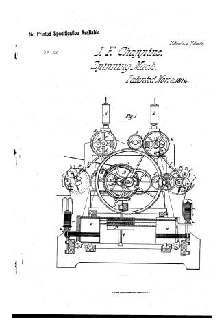 Page 1
-
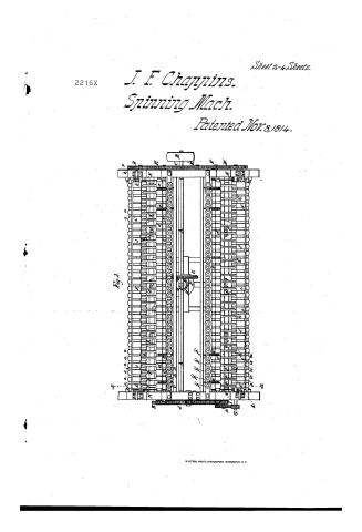 Page 2
-
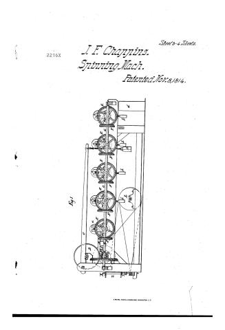 Page 3
-
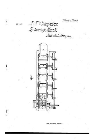 Page 4
-
 Page 5
-
 Page 6
-
 Page 7
-
 Page 8
-
 Page 9


U.S. Patent and Trademark Office · Google Patents
Show the transcription Hide (1,996 words)
Machine transcription (LightOnOCR) of the pages as scanned by the USPTO, most of them the handwritten copies made when the records were restored after the 1836 fire. Not checked; it can misread handwriting, so compare it with the scan.
Page 1.
No Printed Specification Available
2216X
J. F. Chappins.
Spinning Mach.
Patented Nov. 8, 1814.
Sheet 1-4 Sheets.
Fig. 1
M. PETERS, PHOTO-LITHOGRAPHER, WASHINGTON, D. C.
Page 2.
2216X
J. F. Chaykins.
Spinning Mach.
Patented Nov. 8, 1814.
Sheet 2-4 Sheets.
Fig. 2.
Page 3.
2216X
J. F. Chappins.
Spinning Mach.
Patented Nov. 8, 1814.
Sheet 3-4 Sheets.
Fig. 1
Page 4.
2216X
J. F. Chappins.
Spinning Mach.
Patented Nov. 8, 1814.
Sheet 4 - 4 Sheets.
Fig. 2.
Page 5.
Nov. 8, 1814
John Francis Chappeis
Letters Patent
The subscriber is bound to insert this Letters Patent and making part of the same containing a description in the words of the said John Francis Chappeis himself of his machine for spinning Flax & Hemp.
This machine is a system composed of five wooden rollers, and one iron fluted cylinder in front of the machine. This cylinder is 3½ inch diameter and receives pressure from a wooden roller of from 7 to 8 inches diameter covered with leather in order to give it more elasticity at each end of this upper roller is a lever 3 feet long at the end of which is fixed a weight of from 25 to 30 lbs. The five wooden rollers that are fixed on the same principle one after the other at a distance of about 9 inches, are each pressed by another wooden roller on each side of which hangs a weight to give more pressure under the roller to combine the fibres of flax. These weights are of about 7 lbs. The first wooden roller is 3½ inch diameter, the 2nd of 3½, the 3rd of 3, the 4th of 2½, the 5th of 2½ inches. This difference exists in order that each cylinder may have some draft on the next for the purpose of keeping the material always well extended.
These rollers turn by means of a bevel wheel fixed at the end of each, and receiving their motion from other wheels fixed on a shaft that receives its motion from a communication wheel turning with a pinion situated on a shaft of the iron fluted cylinder. The flax that passes between the 5 wooden rollers weighs 15 ounces taking an extent of 12 feet 4 inches. The iron fluted cylinder situated in front of the machine moves 15 times quicker than the 5 wooden rollers by which means the flax passing through the cylinder is 15 times thinner.
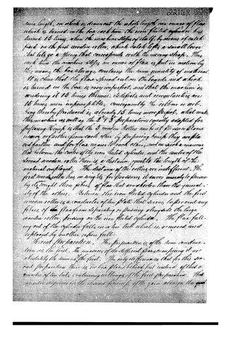
This operation is necessary because the flax entering the machine comes out of a box of 20 feet long placed behind the machine. This box is about 8 inches wide and of a sufficient height to contain the mass of flax that weighs 15 ounces in an extent of 12 feet six inches. On each side of this box is a board of the
Page 6.
same length, on which is drawn out the whole length one ounce of flax which is turned in the box each time the iron fluted cylinder has turned 15 times, when the machine stops of itself, by means of a catch fixed on the first wooden roller, which catch lifts a small lever that lets go a spring that corresponds with the moving shaft. Thus each time the machine stops an ounce of flax is put in motion by this means the box always contains the same quantity of material. It is clear that the flax spread out on the boards and which is turned in the box is very imperfect, and that the machine is rendering it 15 times thinner, its defects and irregularities are 15 times more inappreciable; consequently the ribbon is not being thereby produced is already 15 times more perfect, what makes this machine as well as the 2nd & 3rd preparations equally adapted for preparing hemp is that the 3 wooden rollers can be at pleasure placed nearer or farther from each other by preparing hemp they are placed farther and for flax nearer to each other, and in such a manner that between the centre of the iron fluted cylinder and the centre of the second wooden roller there is a distance equal to the length of the material employed. The distance of the rollers are indifferent. The first wooden roller has no weight for its reasons it serves merely to press by its weight those fibres of flax that are shorter than the generality of the others. Between the iron fluted cylinder and the first wooden roller is a conductor of iron plate that serves to prevent any fibres of the flax from separating or passing alongside the large wooden roller, pressing on the iron fluted cylinder. The flax falling out of the cylinder falls in a low tub which is removed and replaced by another when full.
Second preparation. This preparation is of the same construction as the first. The measures of the different flax comprising it are absolutely the same as the first. The only difference is that for this second preparation there is no box placed behind but instead of that a number of tin tubs containing as long as of the first preparation. This number depends on the desired fineness of the yarn also on the qual
Page 7.
2216X
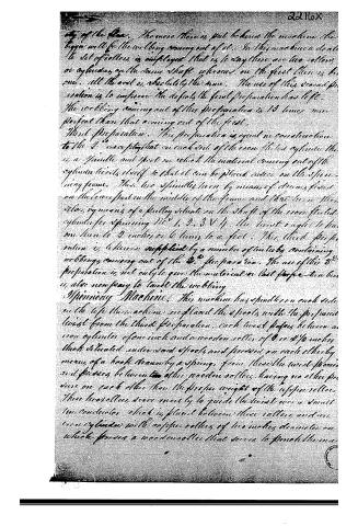
of the Star. The more there is put behind the machine the bigger will be the webbing coming out of it. In this machine a double set of rollers is employed that is to say there are two rollers or cylinders on the same shaft whereas on the first there is but one. All the rest is absolutely the same. The use of this second preparation is to improve the defects the first preparation has left. The webbing coming out of this preparation is 13 times more perfect than that coming out of the first.
Third Preparation. This preparation is equal in construction to the 2nd except that on each side of the iron fluted cylinder there is a spindle and foot on which the material coming out of the cylinder twists itself so that it can be placed easier on the spinning frame. There are 2 spindles turn by means of drums fixed on the lower part in the middle of the frame and there are 2 others, by means of a pulley situated on the shaft of the iron fluted cylinder for spinning No 1, 2, 3 & 4. The twist ought to be one turn to 2 inches or 6 turns to a foot. This third preparation is likewise supplied by a number of tin tubs containing webbing coming out of the 2nd preparation. The use of this 3rd preparation is not only to give the material a last perfection but is also necessary to handle the webbing.
Spinning Machine. This machine has spindles on each side on the top there are 2 spools with the prepared twist from the third preparation, each twist passes between a iron cylinder of one inch and a wooden roller of 8 or 8 1/2 inches thick situated under said spools and pressed on each other by means of a hook drawn by a spring, from there the twist passes and passes between 2 other wooden rollers, having no other pressure on each other than the proper weight of the upper roller. These two rollers serve merely to guide the twist over a small iron conductor which is placed between these rollers and on iron cylinder with copper rollers of two inches diameter on which passes a wooden roller that serves to pinch the ma-
Page 8.
22167
local twist comes out of the iron conductor. This, for some special reason, by means of a hook drawn by a spring fixed on the frame. From this copper roller, the flat yarn on the spindle is twisted below them and that twist it is given.
The wooden rollers situated when the conductor were a little quicker than the copper iron cylinder in order to keep the twist always extended. The iron cylinder with copper rollers delivers thirty times quicker than the iron cylinder, by which means the yarn gets 30 times finer than the twist placed on the machine. By this means, if there was yet any unevenness in the preparation it would be found 30 times more imperceptible in the yarn and 30 times more perfect. Under the cylinder with copper rollers is a box containing water, the copper rollers dipping in this water get wetted, and turning wet the yarn also.
To obtain the different numbers of yarn the preparation twist must be made coarser or finer, on which answers the same purpose is to give to the cylinder with copper rollers more or less quickness in the iron copper cylinder.
Disposition of the wheels. At the end of the machine is a shaft bearing a pulley on which is the moving strap; at the other end is a pinion of 30 teeth that turns each row of cylinders with copper rollers, which each of them have at their end a wheel of 100 teeth. As these wheels of 100 teeth are to turn from the pinion of 30 teeth to catch in one another, it is necessary to place between the pinion and the wheel of 100 teeth a communication wheel of which the number of teeth is indifferent, but one of 100 teeth is convenient to to fill the space. At the opposite end there are two wheels, instead of one in order that the cylinder situated on this side may turn the same way with the opposite cylinder. By this means the cylinders with copper rollers receive their motion. At the end of the machine opposite to the last mentioned wheels, and on the shaft of the last cylinder with copper rollers is a pinion of twenty teeth (this pinion of 20 teeth serves to give 30 strokes) moving with a communication wheel of 60 teeth—on this wheel of 60 teeth, fixed another pinion of 30 teeth moving with a great communication wheel of 252 teeth.
Page 9.
2216X
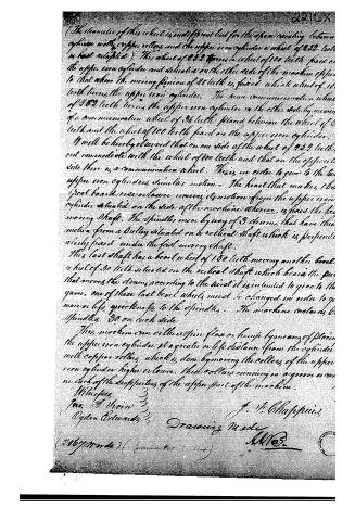
(The diameter of this wheel is indifferent but for the space reaching between cylinder with copper rollers and the upper iron cylinder a wheel of 252 teeth is best adapted.) This wheel of 252 turns a wheel of 100 teeth fixed on the upper iron cylinder and situated on the other side of the machine opposite to that where the moving pinion of 26 teeth is fixed, which wheel of 100 teeth turns the upper iron cylinder. The same communication wheel of 252 teeth turns the upper iron cylinder on the other side by means of a communication wheel of 36 teeth placed between the wheel of 252 teeth and the wheel of 100 teeth fixed on the upper iron cylinder.
It will be hereby observed that on one side of the wheel of 252 teeth, not immediate with the wheel of 100 teeth and that on the opposite side there is a communication wheel. This is in order to give to the two upper iron cylinders similar motion. The heart that makes the foot board rise or lower receives its motion from the upper iron cylinder situated on the side of the machine where is fixed the first moving shaft. The spindles move by way of 3 drums, that have their motion from a pulley situated on a vertical shaft which is perpendicularly fixed under the first moving shaft.
This last shaft has a bevel wheel of 150 teeth moving another bevel wheel of 50 teeth situated on the vertical shaft which bears the part that moves the drums according to the twist it is intended to give to the yarn. One of these last bevel wheels must be changed in order to give more or less quickness to the spindles. The machine contains 60 spindles, 30 on each side.
This machine can either spin flax or hemp by means of placing the upper iron cylinder at a greater or less distance from the cylinder with copper rollers, which is done by moving the rollers of the upper iron cylinder higher or lower. These rollers running in a groove across each of the supports of the upper part of the machine.
Witnesses
Jno. H. Voisin 3
Ogden Edwards 3
J. J. Chapman
Drawing Made
M. B.
(2067 words) (January 1854 - 6.1854)
About this record
- Patentee
- DATAMP
- Date
- the Name and Date index of patents, DATAMP, USPTO records
- Invention
- DATAMP
- Listed in
- the Name and Date index of patents, DATAMP, USPTO records, Jim Shaw's X-patent list, S. A. Elliot's printed list of patents, Burke's List of Patents (1847)
- S. A. Elliot's printed list of patents gives the same name and date.
- Burke's 1847 Patent Office list gives the same patent.