

Drawings and documents
National Archives restored drawings: drawing
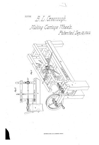
Bracket L. Greenough Patent Drawing for a Machine for Making Carriage Wheels

National Archives, Restored Patent Drawings (Record Group 241) · Full-size scan at the National Archives · Catalog record
Show the text on the drawing Hide (272 words)
Words on the drawing as machine-read by the National Archives; not checked. Useful mainly for searching.
144, WOOD WORKING MACHINES. / wrig / Tenoning and Boring. / #350 / 2378 / BRACKET L, L,un / NOUGH / Fig.2. / Nachine for making Cl / Wheels / 2378-+ / Patented sept 12th 1815 / Vol: 3. page 405 / ION / I, / Reference / Li / 10.00 / Fig. perspective view of machine. / Figh side view of half of machine. / A,A,A,A,A: A,A, A.A: Frame. / Fig 1. / / B,B, two posts. / c,e; two girts / 2X / D,D, two girts in centre of frame... / E,E, square pieces of timber, with keys a,a,a,a,) / G,G, pivots, which confine the nave (H) / T,1, girls, which slide in a mortise (b,b) / c,c,e, tennons / J,J, standards, which pass through mortice (d) / K,K, two keys, / e,e,e, sc, spokes / L, head post, framed into two girls( J.f.) / g.g.g.g. joint bolts - / M.M., carriage framed / h,h, two sticks oftimber. / P, wheel for turning burr mandrill (a)by band / on whirl (i) / S,S, two blocks for the mandrill run in. / t, centre in head post (I) / u, shoulder on mandrill / V, small timber penned through post(L) lever(w.) the one / framed / to / head / the / other / of which is framed into the roller( T) / x, the burr ( Fig. represents a transverse section / of burr) which cuts the lenons on the ends ofspokes. of / t,t, (Fig.2) the teeth on cutting end of cylinder / NL / IL / Patent Office / May 8. & A846 / August A Teachmide Dati / made under the direction of the Commissioner / of Patents in conformity with the act of / 3rd of March 1837
USPTO scan
The patent as scanned by the USPTO
-
 Page 1
-
 Page 2
-
 Page 3
-
 Page 4
-
 Page 5


U.S. Patent and Trademark Office · Google Patents
Show the transcription Hide (1,367 words)
Machine transcription (LightOnOCR) of the pages as scanned by the USPTO, most of them the handwritten copies made when the records were restored after the 1836 fire. Not checked; it can misread handwriting, so compare it with the scan.
Page 1.
2378X
B. L. Greenough,
Making Carriage Wheels.
Patented Sep. 12, 1815.
Fig. 1
Fig. 2
AM. PHOTO-LITHO. CO. N.Y. (OSBORNE'S PROCESS.)
Page 2.
Sept. 12 1845
Sept. 2378x
Bracket & Greenough
Letters Patent
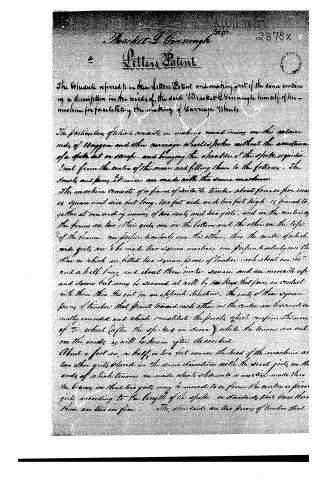
The Vol. 46 referred to in these Letters Patent and making part of the same containing a description in the words of the said Bracket & Greenough himself of his machine for facilitating the making of Carriage Wheels.
The particulars of which consists in making round tenons on the exterior ends of Wagon and other carriage wheels spokes without the assistance of a spoke lathe or stock, and bringing the shoulder of the spoke equidistant from the centre of the move and filling them to the fellows. The dowels and pins likewise are made with the same machine.
The machine consists of a frame of iron or timber about four or five inches square and nine feet long, two feet wide and two feet high, is formed together at one end by means of two posts and two girts, and in the centre of the frame are two other girts, one in the bottom and the other on the top of the frame, one perpendicular over the other, then the centre of which two girts are to be made two square mortises, one perpendicular over the other in which are fitted two square pieces of timber, each about one foot and a half long and about three inches square, and are movable up and down but may be secured at will by two keys that pass in contact with them, then the girt in an opposite direction, the ends of these square pieces of timber that point toward each other in the centre are beveled or nearly rounded and which constitute the pivots which confine the move of the wheel (after the spokes are done) while the tenons are cut on the ends, as will be herein after described.
About a foot and a half or two feet nearer the head of the machine are two other girts placed in the same direction with the first girts on the ends of which tenons are made which slide into a mortise made thru the beams so that two girts may be moved to or from the centre or from girts according to the length of the spoke or standards that have thru them are two or five. The standards are two pieces of timber that
Page 3.
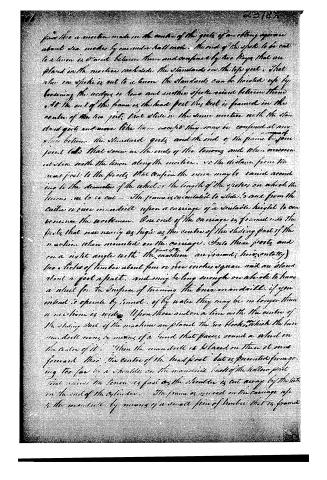
from the a machine made in the center of the girts of an strong square about six inches by one and a half inch. the end of the spoke to be cut to a tenon is driven between them and confined by two keys that are placed in the notches each side the standards in the top girt. That when one spoke is cut to a tenon the standards can be located up by lowering the notches or keys and another spoke raised between them. At the end of the frame is the head post the best is framed in the center of the ten girt that slide in the same notches with the standard girts and move like them except they may be confined at any place between the standard girts and the end of the frame by a joint bolt that screw in the ends of the tenons and then move at the same with the tenon along the notches. as the distance from the head post to the girts that confine the move may be varied according to the diameter of the wheel or the length of the spokes on which the tenons are to be cut — the frame is mounted to slide 3 and from the cutter or vise in a drill upon a carriage of a suitable height to convene the workman. One end of the carriage is framed into the posts that are nearly as high as the center of the sliding part of the machine when mounted on the carriage. Into these posts and on a right angle with the machine are framed (horizontally) two pieces of timber about four or five inches square and an stand about a foot apart. and may be long enough on which to hang a wheel for the surface of turning the burr on a drill. if you intend to operate by hand. if by water they may be no longer than a machine is wide. Upon these and on a line with the center of the sliding part of the machine are placed the two hooks which the burr mandrel runs by means of a band that passes round a wheel on the center of it. When the mandrel is placed on them it runs forward till the center of the head post but is prevented from going too far by a shoulder on the mandrel back of the hollow part that receives the tenon as fast as the shoulder is cut away by the tool on the end of the cylinder. The frame is moved on the carriage up to the mandrel by means of a small pin of timber that is framed
Page 4.
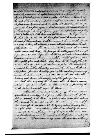
on at the foot of the head post and passes horizontally through a mandrel under the mandrel, the opposite end of which is formed into a lever, the end of which is formed into a roller that turns in a fork at the head of the machine and gives a sufficient purchase by which the frame is easily moved up to the cutter till stopped by the shoulder in the head post against the shoulder on the mandrel back of the cylinder, so that by moving the head post, you may bring short or other edge to the base and cut the tenons. For longer ones or for wheels of greater diameter the head post must be moved nearer the head of the machine, so likewise must be moved the standards and girts to bring the standards a suitable distance from the end of the spoke.
The Burr mandrel is made of iron about a foot and a half long. The Burr on the cutting end of it is a cylinder about an inch longer than the tenons intended to be cut which the cylinder receives, about an inch of the end of the cylinder is steel, three eighths of an inch thick, being twice the thickness of the cylinder from the cutting end to the shoulder or guide. This shoulder is somewhat larger than the cutting end and when the head block is suitably placed, prevents the sliding part of the machine from moving too near the cutter, and comes to a shoulder in the post when the tenon is cut down. The cutting end of the cylinder has one or more teeth that cuts away the shoulder while the tenon is received into it.
The dowels and pins are likewise made by presenting the — the timber of a suitable size to the Burr.
After the spokes are set in the frame, the Burr is placed upon the posts and keyed to it, so that the end of the spoke points directly to the Burr. A spoke is then made fast between the standards. The Burr set in motion, the workman by means of the lever draws up the machine till the tenon is cut on the end of the end of the spoke. The machine is then thrown back by the same means which draws the tenon out of the cylinder of the Burr and now the standards are to be removed and the operation repeated till all are cut. Of convenience, may require this machine with any
Page 5.
little alteration may stand perpendicularly between parts. In this case the left of the sliding part would apply sufficient force to the man's side and nearly the same means might be employed in using it as in this case.
End. Nicholas
H.C. James Wheelock
Stephen W. Kinaman
Bracket Greenough
Dwight Wade
A.M.S.
1386 words
About this record
- Patentee
- Jim Shaw's X-patent list
- Date
- the Name and Date index of patents, USPTO records, Jim Shaw's X-patent list
- Invention
- the Name and Date index of patents
- Listed in
- the Name and Date index of patents, USPTO records, Jim Shaw's X-patent list, S. A. Elliot's printed list of patents, Burke's List of Patents (1847)
- S. A. Elliot's printed list of patents gives the same name and date.
- Burke's 1847 Patent Office list gives the same patent.