

Drawings and documents
National Archives restored drawings: drawing
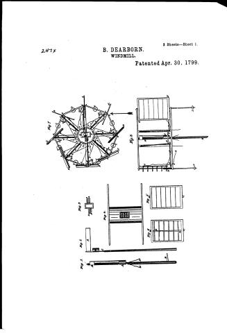
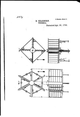
Benjamin Dearborn's Patent Drawing for a Double Centre'd Mill


National Archives, Restored Patent Drawings (Record Group 241) · Full-size scan at the National Archives · Catalog record
Text on the drawing
Words on the drawing as machine-read by the National Archives; not checked. Useful mainly for searching.
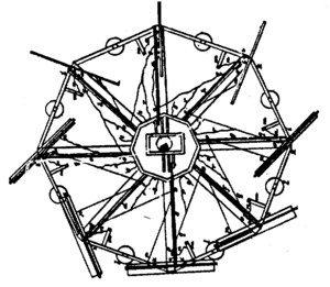
Sheet 1. 98. / ENEO / CLASSIFICATION / [118 / Wind / DIV ISION. / BENJAMEN / all / THE / DOUBLE / CENTRE'D / MILL. / First sheet. / Patented 30th April 1799 / FIG / 7. / B. / FIG.1. / FIG.2. / FIG.3. / A. / FIG.8. / I. / C. / i. / II / FIG.4. / C. / th / 14 / H. / F. / G. / IC 6. / FIG / IC. / FIG / 7. / K. / B. / Jug Is a horizontal section of the Dome, arms. be. of the Hind. mill; / the arrow shewing the course of the wind The position taken by each wing, / in the revolution of the mill is shown by the thick black lines A.B.C.D.E. / F.G H. the order of which describe the motion of the mill, but it can as / easily be constructed to revolve the contrary way. The leaders, which give / the wings their positions, are shown by other thick black lines / f.g h. the leaders are forced outward on one side of the mill, and drawn / in on the opposite, by the directing Names; one of which, only to avoid / confusion in the figure) is shown, at K. which, by turning round the / C. / IC. / excentric circle L. forces outward the leader and draws m the leader.e. / FIG.8. / whereby the wing A is turned, with its broad surface, and the opposite / Ing 1. The shaft of the mill, with the excentric circle A. hanging by a pin / ning E. with its edge to the wine. The small black circle in the / Lug 8. Is a perpendicular section of the Wind mill, shewing only two of / between two proces on the upper part of the shaft, one of which is seen at B / centre, is the shaft, round which the mill turns. The pices are / the leaves; the others being omitted to avoid confusion in the figure. A.B / D.are 2 cords, which pays through the shaft, and are made fast to the excentrie / arles, to which are suspended the certrifugal regulators, or weights- / the shaft; C. the centrifugal circle. D.E one of the directing frames support / circle, cree opposite sides. E. is the lever by which the shaft is turned. / by a bar the end of which is represented, by a square shade, in the cen / -ed by the two pendant precess a.b. and a.d, to which the leaders £. and / Fig 2. Refiresents the shaft, constructed with a fane A. whereby the wind / tre of the circular weights l. This bar mig ht be made sufficiently / attached, giving motion to the two opposite wings; the wing F. G. being thereby / turns the excentrie circle B. round a frin, or rod, which has a shoulder at / heavy to answer the purpose without weights from the astes are ex / turned to face the wind, and the wing H.I. having its edge br aight to the wind. / G. to support the weight of the dome. / tended short frices marked m. which, by the lines open the leaves of the / The wing H.I. has its leaver opened by the line every time the mill / kig Is one of the Ireeting frames; the spaces A.A. ilide on / wings, when the regulators are through outward to a certain degree by / revolves, this line communicating with the next leader, and wing : and / preces within the dome, and prevent the frame from burning. The / the velocity of the mill. Pullich or heaves are represented, on the lead / pafring the sheave or fulley k. The leaves are also, opened whenever / spaces B B. receive the pendant pieces, to which the frame is hung, / ers, and on the arms at o. round there sheaves, the are / the velocity of the mill is too great, by the centrifugal power of the regu / and to which the leaders are attached; this frame lies horizontally in / papied, which being fastened at the end P. to the wing, and at the end / the dome. / lators K.L. from which, lines made fast to the short arm I. and to the line / to the leaves of the next wing open all those, which if shut, would pro / before mentioned, are drawn downward, and open the leaves, when the regula / Iig 4 Is OL representation of the dome and arms; shewing only one / duce resistance in the revolution of the wheel. Thus, the leaves of the / -tors are thrown outward to a certain degree. / pair of arms on each side, to prevent confusion in the figure. / roing C. are seen just opening those of D quite open; those of E begin / The pendant friece C. d. hangs on the opposite ride of the post, although / this 5. Is a front view of one of the wings, with the leavel shut. / ning to close, those of of nearly closed and all the others quite closed. / drawn on this side; as it could not be represented on the other. / Fig 6. Is a front vew of one of the wings, with the leaves open. / The lines Sump r.s. are connected with those last mentioned, and are designed to lead / The above representation exhibits only one wing between each opposite pair / A is the pice on the wing, which opens the leaves. / into through the lower part of the mill; these are to be drawn down,and made fast, when / of arms; but the grms may be extended; and any required number of wings / C.C.C.C. are pinions, on which the leaves turn. / the mill u stopped whereby the leaves will be all opened, and the mill will be / may be placed between them; all being turned by the same machinery within the dome. / secured from moving. The cords, or lines, above described, may be exchang it for / chains, weres, straps thongs, webbing, or any material which will turn round a sheave / or pulley and those parts which do not turn round the sheave, may be supplied / by bars of wood or metal. Some of the motions may also, be produced by angular sroceps, in / the manner simplest. house bells are hung or by axles and arms, as the regulators are fixed; cards and pullies / Vraming Detached
Sheet 2. 30 3°alicet / soapl.,1799 / CLASSIFICATION / Horizontal. / 247-+ / Third, and last sheet. / DOUBLE CENTRE'D MILL. / FIG.13. / F1G.13. / Jig 13. Is a section of a mil, upon a simple construction, of the / foregoing principles, for water, or for the draught,or smoke of a chimney; / but without regulators. If considered as a water wheel, it is a horizontal / section; if as a wheel for a smoke-jack, it is a purpendienlar section. / In this wheel, the arms are mar fast to the shaft, which turns with / the arms; the excentric circle and the firecting frames, being out / side the arms. But one of the directing frames is here shown, to a / voide confusion in the figure. The arrow shows the course of the how / -er which turns the wheel. The excentrie circle is to be fixed, or / movable, as the case may require; but if the power constantly acts / in one direction, it may be fixed for that side which the power requires; / but whether fixed, or moveable the shaft palses through, and turns it. / this wheel may be made with any required number of arms; / and leaves; the parts of which are to nearly similar to those of / figure 11. that they do not require a particular description. / FIG.14. / dug 14. Is the other section of the mill fig.19. If considered cy smoke / jack, it represents the under side, when fixed in the chimney; the / C. / excentric circle A.B. being fixed in the brickwork; and the shaft / FIG. / 14. / passing through it; on the end of which is the perpetual screw. C. / A. / B. / for turning a wheel, on the breast work; with which the spit commu / -nicates, by a chain, or otherwise; or, instead of the screw, a wheel / might be put on, with a groove in it, for the chain, when the inke / 18 This References. Diagram had neither figure, or / -rior fireplace. form of the chimney throws the wheel over one side of the / If this figure be viewed on as a water-wheel, it is a perpendicular / section; the 9. shaft passing up through the excentrie circle; and to / be continued as high as necepary; upon which is fixed a stone for / grinding; or a wheel for turning other machinery or both. / To avoid confusion, but two of the arms are shown in this figure, / with their leaver; which are open, one side; and shut, on the other; / the leaves being turned by pieces outside the arms; which are fastened / to the directing frames, as shown in figure 13. / In the foregoing To this figures, I subscribe, but few as Inventor of the variations the are shown to which the principles are applicable; as they admit of unlimited / of Machines, and author of the descriptions. and herein given. variety. / Benjamin Dearborn.
Sheet 3. 2'aliect / 98. PNEUMATICS. / B. / [118] Wind Wheels. / Horizental / Second sheet. / DOUBLE CENTRE'D MILL. / CLASSIFICATION / C. / FIG.9. / FIG. I. / Fig 9. Is a houzontal section of a mill, with only six wings, as the num / FIG. 11. / 247-7 / DIVISION. / ber may be varied, at pleasure. She wings are formed with leaves turning / on horizontal arles; but they do not turn on perpendicular arles, as those of fig.7 / C. / all of them being on a line with the arms, in all parts of the revolution, with / one pinion of each leaf resting in the side of the dome; and the other in a per / pendicular price fushened to the extremity of the arms. The leaves are formed / as those of Frig 7. One shutting against another by their own weight. They / are opened by lines, communicating with the machinery within the dome which / machinery is similar to that before described; there lines hafs through pullies, / or sheaves, fastened on the arms, by pieces, represented 4 at a.b.c f. / C. / E. / The arrow shows the course of the wind; and the leaves of the arms A. / and B. are shut, facing the wind, and receiving its power. The leaves of / C. are just opening; the leaves of D. and E. are quite open and the / leaves of F. are just closing. The centrifugal regulators are fixed as before / f. / described; here. and operate in the same manner, therefore they need not a description / FIG.11. 11. / Fig. 11. Is a horizontal section of a mill, with perpendicular haves, and / only four pair of arms; which number as also, the number of leaves, may / be increased, or deminished, if the constructer chooses. The arrow shows / the course of the wind; the leaves on the arm A being shut, facing the wind, / g. / and those opposite, on the arm B. being quite open. The leaves on the / other arms appear at an angle of forty five degrees with the arm, those on / A. / C. being opening; and those on D closing. The liaves opposite to those which / D. / receive the power of the wind, are opened by machinery within the dome, / h. / i. / l. / similar to that before described, which draws the cords, chains, or straps a b. / FIG.12. / FIG. / 10. / c.d. beside which, there are others to draw the leaves open, when the / mill is stopped which may be done by a friction bar, or band, rubbing a / E. / B. / gainst the cog wheel. The leaves are, also, opened when the velosity / of the mill is sufficient, by the centrifugal power of the regulators; as will / be better described, in kigure 12, and they are that by the weight, or yra / vity of the same regulators when the centrifugal power is reduced / The braces A.C. c.B. B.D. and D.A. are added, to brace the arms; and to / that support the regulators; these braces may be nearer the centre; / receive pieces shown in Fig 12. in which one end of the axles are hung but / Lt. / L. / L. / this mill, the contrary of that shown before; as may be seen by the figure; / the power of the regulators will then, be lefs. A direction is the Ao / n} / the principles being applicable to a motion with the course of sun, / E. / B. / or against it. The frieces e f h. are axles, to which the regula / E. / tors are attached; only two of these axles are seen in the next figure. / G. / H. / The four circular black spots, marked i.k partly seen, near the / ends of the arms, are the regulators; which are seen in the next figure, / each marked by the same letter The thick black lines A.a B.b. C.c. / and D.d. are horizontal bars; which communicate with the leaves, and open / them by means of a piece, turning on a centre, shown in figure 12. which is / fastened to the bars, at its upper end! B. The excentric circle of this / m. / FIG. 10. / Jug 10. Is a perpendicular section of the mill shown in figure 9. / mill; as well as all the others may be made to turn with the wind. / FIG.12. / The liner showing the parts of the two figures which correspond with each other. The / Jrg. 12. Is a perfundicular section of the mill above described, in which are / wings B.B. and E E. are partly hidden by the nrngs A and F. F. which, standing obliquely, / shown the leaves of the arms A. and of Figure 11. and one leaf of the arm D. the other leaves being hudden behind it. / In this figure, the manner of affixing the centrifugal regulators is more clearly shown, than it could be in the last figure, / are foreshortened in the figure. Two circular black spots, over G and H. represent the sheaver, / it is as follows E and F. refresent two pieces, seen sidewise; which, for distinction, I denominate Buttons; they may be / over which the lines, or cords pafs, which communicate with the Machinery within the dome. / The excentric circle; and the frecting frames being similar to those, before described, are not here / made solid, as refresented in the figure or may be made with frame work. Pach regulator hangs on a pin, which palses thro' / represented. The manner of hanging the anles, to which the regulators are suspended could not / the button near its edge; through a hole near the opposite edge an axis is passed; with which the button turns. The axis / hangs in two frieces projecting downward one in the arm, and the other in the brace, as seen atG and H. where two / be shown in the figure; they may be hung in the sides of the arms; or, in pieces nailed on the arms; / opposite regulators are shown. The top of each button communicates with one of the horizontal bars, which open the leaves, by a / or, in rtaples, driven into the under part of the arms; or, in any other way, more convenient; they / card, or otherwise. Toward the bottom of the button is another card, or chain Sic which is made fast to the bar of the regulator; / may, also, turn on fins, or on their ends being made round. But three of the six regulators, / are shown, in this figure; the other three being imposed to be hidden behind those. The frieces / and is seen, hanging look, at I.andK. By the length of this card, or chain, is determined the angle at which the regulators / on the back of the leaves, which are drawn downward to open the leaves, are, in all these figures, re. / shall begin to open the leaves; the cord is, therefore, paped through a hole, in the button, to be lengthened or shortenic at pleasure. / presented as made of wood; but they may be made of cord, strapt, were, or of metal bars, or sheets. / each leaf, is seen a notch, of the corner, for the convenunce of bringing the bar which opens them nearer to their contre than it could otherwise, be, / Thus, the regulators operate by two powers; their gravity, or weight, shutting the leaves, until Huir centrifugal force opens them. Att / unlefs the whole leaf was shortend. four cords, are seen atn.o.p.q. which haps through the dome to the lower part of the mill it, by drawing all the leaves open. / 613
USPTO scan
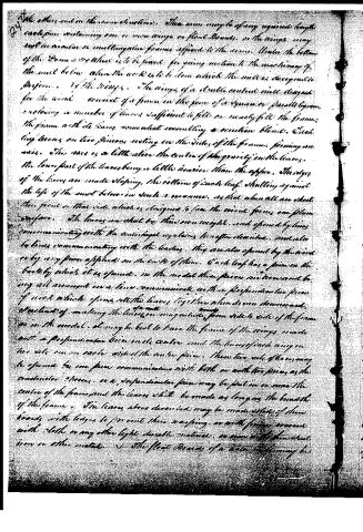
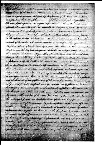
The patent as scanned by the USPTO
-
 Page 1
-
 Page 2
-
 Page 3
-
 Page 4
-
 Page 5
-
 Page 6
-
 Page 7
-
 Page 8
-
 Page 9
-
 Page 10


U.S. Patent and Trademark Office · Google Patents
DATAMP: illustration
Illustrations from DATAMP

DATAMP (Directory of American Tool and Machinery Patents), via the Internet Archive · Archived DATAMP page
About this record
- Patentee
- DATAMP
- Date
- the Name and Date index of patents, DATAMP, USPTO records
- Invention
- DATAMP
- Listed in
- the Name and Date index of patents, DATAMP, USPTO records, Jim Shaw's X-patent list, S. A. Elliot's printed list of patents, Burke's List of Patents (1847)
- S. A. Elliot's printed list of patents gives the same name and date.
- in_burke