

Drawings and documents
National Archives restored drawings: drawing
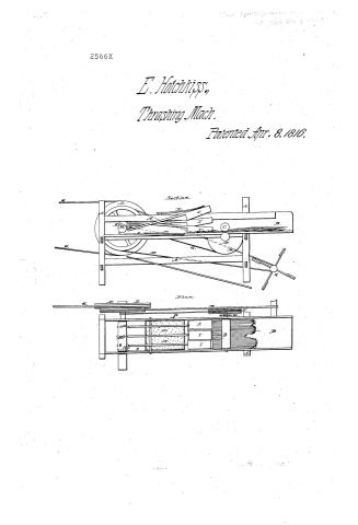
E. Hotchkiss' Patent Drawing for a Machine for Thrashing and Fanning

National Archives, Restored Patent Drawings (Record Group 241) · Full-size scan at the National Archives · Catalog record
Show the text on the drawing Hide (116 words)
Words on the drawing as machine-read by the National Archives; not checked. Useful mainly for searching.
Entered / Yol.3.r 517 / 130. THRASHING. / $2 / Thrashing Machines. / B. Flail Machines. / 2566 / E O HOTCHKISS / CLASSIFICATION / 2566.7 / LIVISION. / Thrashing Fanning / Patented S "Ajurit 1816) / Section / Plan / A Frame / da / B. Straw Box / HD / DC / C. LOWETOT bed Cylinder / D. Uper Cylinator / E. Cny gearing / F Woodru Wheel / G. Bands / H. Main shaft / I Throshing hammers / K Kams / I. Bailonce Wheel / NC. Bandpofung to FanningMill Shaft / N. Riadle Screen / 0. L. ever giving motion Γo Screen / Patent office Mar o2 1840 / P. Cheoh shrings / Q. Fan. / Made under the direction of the commysions of / Strickland Del / paterbs in conformity with ach of 3ʳᵈ March 1834- / Commissions of hatults
USPTO scan
The patent as scanned by the USPTO
-
 Page 1
-
 Page 2
-
 Page 3


U.S. Patent and Trademark Office · Google Patents
Show the transcription Hide (848 words)
Machine transcription (LightOnOCR) of the pages as scanned by the USPTO, most of them the handwritten copies made when the records were restored after the 1836 fire. Not checked; it can misread handwriting, so compare it with the scan.
Page 1.
2566X
E. Hotchkiss,
Thrashing Mach.
Patented Apr. 8, 1816.
Section.
Plan.
Page 2.
Old 8 1816 25660X
Oliver Hatchkiff
Letters Patent.
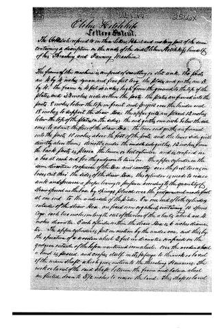
The Petitioner referred to in the Letters Patent and making part of the same containing a description in the words of the said Oliver Hatchkiff himself of his Threshing and Fanning Machine.
The frame of this machine is composed of two parallel or side work. The posts are 4 by 4 inches square, and five feet long. The plates and girts are 3 by 4. The frame is 4 feet or inches high from the ground to the top of the plates, and 23 inches wide within the posts. The plates are framed into the posts 8 inches below the top in front, and project over the inside and 18 inches to support the straw Box. The upper girts are placed 12 inches below the top of the plates on the sides; the end girts one inch below the side ones, to admit the fire of the straw Box. The lower end girts are framed into the posts 10 inches above the foot of the posts, and the lower side girts directly above them; directly under the inside side girts, 12 inches from the back posts is placed the lower or bed cylinder, and is confined in a box at each end for the guigeon to turn in. The upper cylinder in the same direction as the lower of the Box, and exactly over the first turning in boxes cut thro’ the sides of the straw Box. This cylinder is made to reverse drive and pressure a proper bearing or pressure according to the quantity of straw spread in the box, by springs placed over the guigeon and made fast at one end to the underside of the plates. On one end of both cylinders outside of the straw Box, are fixed iron cog wheels containing 10 pins each, each lies inches in length out of the rim of the wheels which are 4 inches diameter. Each cylinder within the straw Box is 6 inches diameter. The upper cylinder is put in motion by the under one, and this by the operation of a wooden wheel 2 feet in diameter confined on the guigeon outside of the before mentioned iron wheel. Over the wooden wheel a band is passed, and crosses itself in its passage to the neck or barrel of the main shaft which gives motion to the threshing Hammers. The neck or barrel of the said shaft between the frame and balance wheel are fluted down to 3½ inches to receive the band. This shaft or barrel
Page 3.
is 4 feet long and 6 inches in diameter, has its bearing or fulcrum at the
four end of the machine, in the centre of the shaft and any from the plates
are inserted 3 sets of Hams of 3 Hams in a set, placed at proper dis-
tances to operate upon the hams of the hammers when motion is similar
to a black smith's trip Hammer. On the further end of the shaft is fix-
ed a balance wheel 48 inches in diameter constructed with four arms
and felloes, 6 inches thick and 8 wide. The outer surface is divided &
fitted to receive two bands, one cover larger than the other & on the
outside gives the first motion, and is adapted to either horse or water
power. The larger or inside cover receives a band passing over it to a
wheel about 3 inches in diameter on the end of the fanning mill shaft
the box extends 2½ feet beyond the hind end of the frame over the
fanning mill, which is constructed like a common dutch winnowing
mill. Directly in front of the 3 cylinders is placed three wooden
hammers or mallets of an exact thickness and just sufficient to fill up
the straw box 4½ inches wide and 1½ inches long with shafts or handles 3½
feet long, the shafts are hung at 10 inches from the fore end upon a guide to
receive the hams which give them motion like the trip Hammer.
Directly in front of the hammers is a middle screen or sieve made of sheet
iron, over which the straw passes after the operation of the hammers and
through which the grain is sifted into the fanning mill a quick movement
is given to the screen or sieve up and down by means of a lever hung on
a pivot near the centre thereof, and this lever obtains its motion from
the operation of 12 small cogs inserted in the further end of the Barrel
shaft & inside of the straw box. Over each hammer is fixed a
check spring like a habit to a forgerman's Hammer. It is not conve-
nient necessary to describe that part of the machine which employs the
fanning mill, those mills being so commonly in use thro' our country
that almost all persons must have a knowledge of them.
End.
Witnesses
Stephen Greenleaf
Sam Elliot
Elisha Hotchkiss
About this record
- Patentee
- the Name and Date index of patents
- Date
- the Name and Date index of patents, USPTO records
- Invention
- the Name and Date index of patents
- Listed in
- the Name and Date index of patents, USPTO records, S. A. Elliot's printed list of patents
- S. A. Elliot's printed list of patents gives the same name and date.