

Drawings and documents
National Archives restored drawings: drawing
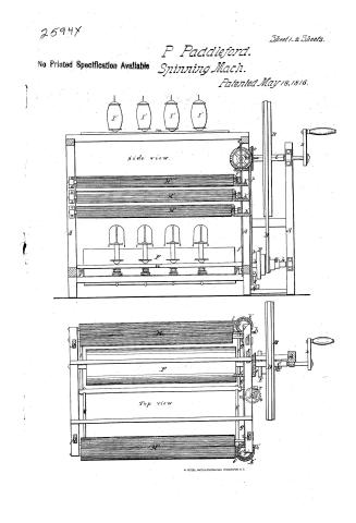
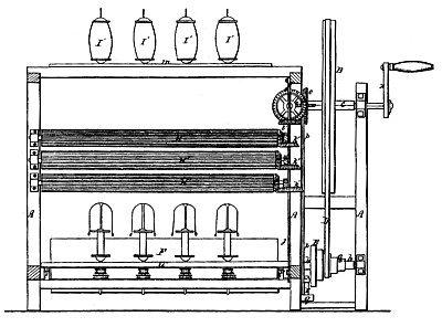
Peter Paddleford's Patent Drawing for a Spinning Machine


National Archives, Restored Patent Drawings (Record Group 241) · Full-size scan at the National Archives · Catalog record
Show the text on the drawing Hide (342 words)
Words on the drawing as machine-read by the National Archives; not checked. Useful mainly for searching.
Sheet 1. CLASSIFICATION / 2594X X / DIVISION. / # 2.5-94x / 2 Sheets-Sheet 1. / P. PADDLEFORD. / SPINNING MACHINE. / Patented May 18, 1816. / I' / I' / I' / I' / side view / Top view
Sheet 2. with 2594-X / 2 Sheets-Sheet 2. / P. PADDLEFORD. / SPINNING MACHINE. / Patented May 18, 1816. / I' / DO / End view / 70 / a. / 911
Sheet 3. SEIFICATION / POTER P / MCFORD / 2594-1 DIVISION / Spriming Tip / Machine for of / ring sheep's / 118. SPINNING. / [142] Throstles & Caps / wool and / on / Peter / Patented May 18th 1816 / Vol 3 page 497 / at, may / I' / side view, / A. / End VI PW . / LO / Reference / A.A.A. FC Six posts. / B, large wheel, working onhorizontal axi3 Cen / D, band, which passes round a conical whirl, E / meveably fixed by means of screw (a) one axis. be / of main cylinder. F. :-round which are placed bands / for turning the spindles & fliars d,d,se) / e, faced saywheet. which gears or matches in cog wheel(f) / fixed 072 horizontal shaft( g.) / h,h', wheels fixed on each end of shaft(g.) which turn other / on perpendicular shafts / k'k',k'. K.k.k. three wheels fixed on shafts joj.) each of / Top view. / which goor with other wheels (2'2'2'. 2,2,2,) on feeding rollers, / H'H'H'H',H,H,H,H, three set of feeding rollers firmly fluted / spools on plalform( m) ( shown (ii top & side views), / n, endles screw on shaft(g)- / 0, toothed wheel, on shaft(p) / q, heart, on lower end of shaft(p) which opera. is on an arm(r) / with friction pullry(s) & arms(l,t,)ve for raising and lowering / the spool boards -( u',u,) x crank- / August A. Von Schmidt Del: / Each thread paper thro three pair of fluted Rollers which by reason of the difference in size of the wheels K,K,K,Se_ / on the perpendicuire aris j.j. have difference in the speed with which they revolve; thereby drawing out the warpons / Patent Office / august 12 1846 / made under the direction of the commifrioner / of Patents in conformity with the act of / 3nd of March 1837e / Rume
USPTO scan
The patent as scanned by the USPTO
-
 Page 1
-
 Page 2
-
 Page 3
-
 Page 4


U.S. Patent and Trademark Office · Google Patents
Show the transcription Hide (668 words)
Machine transcription (LightOnOCR) of the pages as scanned by the USPTO, most of them the handwritten copies made when the records were restored after the 1836 fire. Not checked; it can misread handwriting, so compare it with the scan.
Page 1.
2594Y
Sheet 1-2 Sheets.
No Printed Specification Available
P Paddleford.
Spinning Mach.
Patented May 18, 1816.
side view.
Top view
Page 2.
2594X
Sheet 2-2 Sheets.
P. Paddleford.
Spinning Mach.
Patented May 18, 1816.
End view
Page 3.
May 18, 1816
Peter Paddelford
Letters Patent
259AX
May 18, 1816
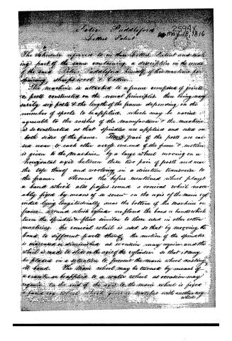
The invention referred to in this Letters Patent and making part of the same containing a description in the words of the said Peter Paddelford himself of his machine for spinning, shreds wool & Cotton.
The machine is attached to a frame composed of joints & posts constructed on the usual principles, there being only nearly six posts & the length of the frame depending on the number of spindles to be applied, which may be varied agreeable to the wishes of the manufacturer & the machine is so constructed as that spindles are applied one side on both sides of the frame. Two pairs of the posts are raised near to each other across one end of the frame & motion is given to the machine by a large wheel moving on a horizontal axis between these two pairs of posts and near the top thereof and revolving in a direction transverse to the frame. Around the before mentioned wheel plays a band which also passes round a conical wheel moveably fixed by means of a screw on the axis of the main cylinder lying longitudinally near the bottom of the machine or frame, around which cylinder are placed the bands which turn the spindles & flies similar to those used in other cotton machines. The conical wheel is used so that by moving the band to different parts thereof, the motion of the spindles is increased or diminished as occasion may require, and the wheel is made to slide on the axis of the cylinder, so that it may be placed in a situation to prevent the main wheel wasting its band. The main wheel may be turned by means of a crank or be applied to a water wheel as occasion may require. On the end of the axis to the main wheel is fixed a face key wheel which gives a motion with another key wheel.
Page 4.
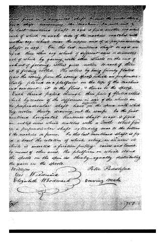
wheel fixed on a horizontal shaft to move the entire string
down shaft transverse the machine. On each end of
the last mentioned shaft or axis is fixed another cog wheel
each of which on each side of the machine matches with
another cog wheel near the upper end of a perpendicular
shaft or axis. On this last mentioned shaft or axis are
fixed three other cog wheels of different sizes or diameters,
each of which by gearing with other wheels on the end of
each set of feeding rollers gives motion to each of three
set of feeding rollers. The rollers by being firmly fluted
draw the roving from the roving spools which are perpendicular-
ly placed on a platform on the top of the machine
and conduct it to the flairs, & thence to the spools.
Each thread passes through three pairs of fluted rollers
which by reason of the difference in size of the wheels on
the perpendicular shaft have an effective speed with which
they work, thereby drawing out the warp. On the first
mentioned horizontal transverse shaft or axis is fixed
an endless screw which matches with a tooth wheel fixed
on a perpendicular shaft extending near to the bottom
of the machine or frame. On this last mentioned shaft is fixed
a bevel the rotation of which, acting on an arm in
which is inserted a friction pulley, raises and lowers,
by means of other arms, the platform on which stand
the spools on the spindles thereby equally distributing
the yarn on the spools.
Witness
Geo. Woodward
Elizabeth Woodward
Peter Paddock
Drawing made
1750
DATAMP: illustration
Illustrations from DATAMP


DATAMP (Directory of American Tool and Machinery Patents), via the Internet Archive · Archived DATAMP page
About this record
- Patentee
- Jim Shaw's X-patent list
- Date
- the Name and Date index of patents, DATAMP, USPTO records
- Invention
- DATAMP
- Listed in
- the Name and Date index of patents, DATAMP, USPTO records, Jim Shaw's X-patent list, S. A. Elliot's printed list of patents, Burke's List of Patents (1847)
- S. A. Elliot's printed list of patents gives the same name and date.
- Burke's 1847 Patent Office list gives the same patent.
- Residence from Burke's 1847 Patent Office list; the standard lists give none.