

Drawings and documents
USPTO scan
The patent as scanned by the USPTO
-
 Page 1
-
 Page 2
-
 Page 3
-
 Page 4
-
 Page 5


U.S. Patent and Trademark Office · Google Patents
Show the transcription Hide (1,559 words)
Machine transcription (LightOnOCR) of the pages as scanned by the USPTO, most of them the handwritten copies made when the records were restored after the 1836 fire. Not checked; it can misread handwriting, so compare it with the scan.
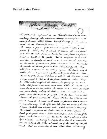
Page 2.
United States Patent
Patent No.: X2602
Philo Clinton Curtis
Patent
The Schedule referred to in this Patent and making part of the same containing a description in the words of the said Philo Clinton Curtis himself of his invention in the Water Frame.
The long or frame of the loom is composed simply of four pieces of timber two of which I term the end pieces and two the side pieces or bars, two end pieces are proportioned in length to the width that is necessary to be woven and have a mortise in each end to receive the side bars in the centre of each end piece there is a tenon that enters the mortise in the end pieces so that when put together they will form a square or an oblong square the frame may be either joined or screwed together with joint bolts or near the centre of this frame I place a wheel the Diameter of which is large enough to slide on to the frame within this wheel I hang two rollers which supports the loom for springing the reel within this frame and near each end I place the cloth and yarn beams or rollers within the wheel and between the cloth and yarn beams I hang the lathe or battin on rods or in a groove and let it slide parallel with the loom or side bars between the yarn and cloth beams I place two rollers or rods which may be wound with wire or formed into a screw in any other way to the right and left from the centre of the loom between the lathe and cloth roller which serves for templing the cloth to operate the lathe there is a roller placed in back of the yarn beam that extends from side to side of the frame and has a lever in the centre that is operated upon by a circular inclining part of the loom there is a connection from the lathe to the roller at each end of the lathe by two pit (many) that are connected to two that lever in the end of
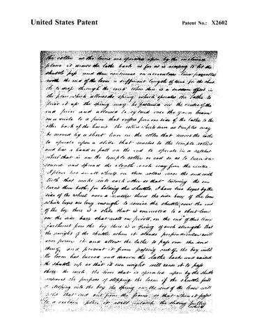
Page 3.
United States Patent
Patent No.: X2602
the roller as the loom is operated upon by the incline plane it draws the lathe back as far as is necessary to let the shuttle pass and then continues on a circular line parallel with the end of the loom a sufficient length of time for the shuttle to drop through the race when there is a sudden effect in the piece which allows the spring which operates the lathe to draw it up the spring may be fastened on the center of the end piece and allowed to expand once the yarn beam on a circle to a piece that varies from one side of the lathe to the other back of the loom the rollers which serve as temples may be moved by a short lever in the roller that moves the lathe to operate upon a slide that reaches to the temple rollers and has a hand or ball on the end to operate in a retort wheel that is on the temple roller or rod so as to turn in round and spread the cloth each way from the center.
I place two small wheels on these rollers near the end with teeth that make into each other so that turning the one turns them both; for holding the shuttle, I have two boxes by the side of the wheel over a distance then the side bars of the loom which boxes are long enough to receive the shuttle over the end of the box there is a slide that is connected to a short lever on the side bars that rests on pivots, on the end of this lever farthest from the box there is a spring of such strength that the weight of the shuttle when it stands perpendicular will over power it and allow the lathe to pass over the end there and prevent it from passing out of the box until the loom has turned and drawn the lathe back and raised the shuttle up so that its own weight will cause it to pass there the more the lever that is operated upon by the shuttle induces the purpose of stopping the loom if the shuttle falls or drops into the box the spring on the end of the lever will hold that end out from the frame so that when it passes to a certain place it will uncatch the sliding pulley which
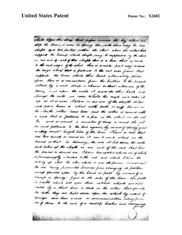
Page 4.
United States Patent
Patent No.: X2602
which takes the strap that passes around the big wheel and stops the loom; in order to spring the cloth there may be two shafts and two pulleys within the wheel above the rollers that support the harness which shafts may be supported by the wheel, on one end of each of these shafts there is a lever that extends to the out-edge of the wheel there is a circle part way around the large wheel that is fastened to the out-side frame that supports the loom which these levers alternately slide upon there is a connection from the pulleys to the harness rollers by a cord strap or chain so that when one of the levers turns upon the circle it draws the other back and springs the cloth, in order to hold the rope and take it up as it is woven I place on one end of the cloth roller and yarn beam a wheel with teeth or cogs the one on the cloth roller turns loose and the roller is turned with a cord that is fastened to a pin in the wheel on the roller and is wound a number of times around the roller and fastened to the pin again, by means of spring generating screw lengthwise of the loom I have a rod that has two screws or worms on it one to each wheel on the harness so that by turning the rod it lets down the cloth and takes up the cloth, on one end of the rod that has the worms or screws on I place two ratchet-wheels one of which is permanently attached to the rod and which I turn the taking up wheel the other wheel is near the former incoimound the rod being prevented however from changing its position unless operated upon by the hand or pull by means of a clamp or spring fixed to the side of the loom the pulls or hands which act upon these ratchet-wheels are separated by a short lever or stud in the roller that operates the latter they are kept down upon the wheels by means of springs and have a cord or communication rising from one of them to the end of a variable brake and descending from
Page 5.
United States Patent
Patent No.: X2602
from the opposite end of said brake to the other part or hand so that when one hand is depressed by the spring into the notch of its ratchet wheel one only of the hands or balls acting upon its wheel at one time; the means in which these ratchet wheels move round the race has its periphery so divided into teeth that the full swing of the lathe just shaves the ball or hand so far back as to remove it one notch and suffer the hand to fall therein and so as to keep the other ball or hand which would act upon the taking up wheel out of the teeth thereof when however so much of the teeth is worn that the lathe cannot have its full swing the ball or hand does not enter the notch in the moving ratchet wheel but will fall into the notches thereof and the moving back end of the lathe will properly the ratchet wheel by means of the hand or ball and so much of the teeth will be round upon the rollers as will allow the lathe bottom again to have its full swing and the hand or the moveable ratchet wheel to have its operations the frame calculated to support this loom may be simply parts set in the building when it is used for the pivots to rest and turn in or a frame calculated for that purpose the boy for the shuttles may be either attached to the lathe and move with it or fastened to the side pieces or bars of the loom the spring to drive the lathe may be in any form best calculated for the business to be performed the power applied to these looms may be done either by straps round the big wheel on the loom or by a wheel or one of the bearings the frame employed to move these looms may be either manual or that of horses, mules, water or steam as shall be thought most convenient in the factories where they shall be introduced
Witnesses: Joel Jones
Silas Curtis
Philip E. Curtis
About this record
- Patentee
- Jim Shaw's X-patent list
- Date
- the Name and Date index of patents, USPTO records, Jim Shaw's X-patent list
- Invention
- the Name and Date index of patents
- Listed in
- the Name and Date index of patents, USPTO records, Jim Shaw's X-patent list, S. A. Elliot's printed list of patents, Burke's List of Patents (1847)
- S. A. Elliot's printed list of patents gives the same name and date.
- Burke's 1847 Patent Office list gives the same patent.