

Drawings and documents
National Archives restored drawings: drawing
Ira Draper's Patent Drawing for Improvements in Weaving

National Archives, Restored Patent Drawings (Record Group 241) · Full-size scan at the National Archives · Catalog record
Show the text on the drawing Hide (796 words)
Words on the drawing as machine-read by the National Archives; not checked. Useful mainly for searching.
84. / F2,608X / IRA DRAPER / Reference / IMPROVEMENT: WEAVING / A.A. Front posts / of of planks / red June 7 page / C.C, / Back / posts / D.D / R.E / Cross / bars / a the breast beam which 23 composed of three narrow beards; / b, / the top board of breast beam, fastrued on ends of posts A,A, / c. / bettom board / d, / narrow board, placed between and atthe bock of them / E'. / represents the layor or bratery- e shuttle ox. / f, / shuttle rod screwed firmly the end of shuttle box g. / Fight View of Loom with one side taken oute / eather end is secured by a bended iron on front of the layor / Γ, scren smut for securing the shaltle box at one end into the layor- / Fight Enlarged view of breast beam / the other end is fastened by a screw / K steel spring inside of shuttle box. with regulating screw Γ., / m, groove for the picker blocks to play in as in other leems / n, wooden spring for throwing The shuttle / crescent or simicirele. pivoted on front of ther breast beam / between the top v bettem beards ot which the breast beam is composed / tick rhand tastened on under side of cresent and extending / beler the layor- this hand has sti ings fastened 10 each of the / J2 / picker blocks to give the hand q the requisite force / the hooks S.S. are pivoted at each horn of the cresent. 70 / which hooks play through the mortices t, and project beneath the / layer. To elevate the two hooks successively there are two levers / u.u. on back of breast beam of ther first order). connected by strings. V.V. / Figh / to light levers W.W. letthe order) which are connected by / strings. x.x. to the treadles z. x2 button,which prevents hooks / 20 / a'., long herizon lal mortice for the hand-q to more through. / 20 / the hooks S.S. catch the wooden spring " alternately / G, yarn beam, with small divisions turned in it b' b'.b'oc these groeves / receive hoops of uron or which are hinged together in two / sideview of Circular brush SEC, / or three pieces (Fig 7-) to clasp round the yarn bram edgewise- to constitute Thin separations 7 44 the warp screw for holding the hoop logether. / Fight.- represent the muche " for "ing the trash (in the different jacks views... ) 4.4. two narrow pieces which of inetal, drilled with heles of common knitting needle / and about twice the distance apartance in which are placed with their ends bent to form eyes through the yarn or threads arepassed. two wires. to keepthr / threads suspended; heard with notches cutout, to receive the ends of every other one of jacks 5.5.5.500, 8.8.8. tally wheels .... / Figh / g talloy 10.10.10. pattser hands 16 held on lo Tito taliry wheels H'. H, grooved rollers, for receiving a band the grooved roller H'AS fixed on / cloth beam I;and the oth roller m yarm beam, a / K, block and fever for tightening / the band L.fr iction placed at the crossing of band. / x,x, temples, (Figs / Fig2. Top virwof hoom / LP / Fig 8 / Pig.6 / Fig.5 / Topview of shuttle box / the / Figg / Figh / Fro 10 / Fig 7. / roller, covered with teather also the yarn beam) / Patent Office / thich dips in the trough N... containing size orpaste for sizing the yorn / to the treadles by cords...e'e', one shaft to each treadle / rfore itpasses the harness- P. Circular brush for brushing the web / aug: 19 1846 / which turned by the motion of ihe tecadles / Fight 8. vilus of temple, a" ring of metal with sharp treth on / 'f'. two whirls on end ot shaft of ircular brush P. having grooves in each / the flat of thir ring, b".cap c".e" two flat lips d.d". grooves. / made under the direction of the Commisioner / k!h'. two clicks...which catch in ath yn shaft of circular brush / e",c", screws ye... dm grove in breast bram 8'. spring which holds / of Patents in conformity with the act / and andround which thry are torrot over the treadles z.z. are / w..clasp, to force the cloth down upon the toeth by the screw.r'. A8 whirl to turn / on teeth eie circumt rence of temple Epicer with circular gatter / 93.9 March 1887 / two cross shafts A'A', d',d, cords made fast to ends of cross shafts / Dª, with small shaft whirl of brush and P. B². hub with grooves.for band (shown in Pig.2.). wairl schub- / with a double turn round the white these cross at ached / H? spindle r², which has an eye at end 2 forthe thread to pass through / Durke / revolving give motion to spinging swifts ve...... K2 small whirl on axis of cam / Consufsioner Patents
USPTO scan
The patent as scanned by the USPTO
-
 Page 1
-
 Page 2
-
 Page 3
-
 Page 4
-
 Page 5
-
 Page 6
-
 Page 7
-
 Page 8
-
 Page 9
-
 Page 10


U.S. Patent and Trademark Office · Google Patents
Show the transcription Hide (3,554 words)
Machine transcription (LightOnOCR) of the pages as scanned by the USPTO, most of them the handwritten copies made when the records were restored after the 1836 fire. Not checked; it can misread handwriting, so compare it with the scan.
Page 2.
June 1816 2608X 52
The Order of a citizen of
Letters Patent.
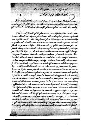
The Schedule referred to in these Letters Patent and making part of the same, containing a description in the words of the said Mr. Orper, himself of his improvement in weaving.
The front posts of the frame are no higher than the breast beams to which they are fastened, the sides of the frame are planks having tenons to enter the front posts in a square direction being united at the other end with tenons to enter the back posts; the back posts are placed oblique (towards) the leg of the back posts & front posts being wide apart; the top end of the back posts being the support of the lay or beater and the lower end being sufficiently oblique, to receive the axis of the yarn beam; from the plank to the back posts a brace is inserted on each side, either straight or curved as to not to permit the swing of the lay or beater in weaving. The two back posts are united by cross bars, one at the top or near as the swing of the lay will permit; the other near the bottom, so far below the yarn beam as to give room for the motion of the tangles which are attached to it. The breast beam is formed of three narrow boards; the top board is fastened on the ends of the said posts which support it; the bottom board is inserted at each end into those posts parallel to the top & about 2½ inches distant from it [a space being between them sufficient for the movement which impels the shuttle] between the top and bottom boards a narrow board is inserted the whole length; the three being united together, sufficiently firm for a breast beam; the strip of board between is put at the back of the others and must have three mortices through; as will be described in the article describing the throwing the shuttle, the part of the beam will then remain open, for the convenience of unchanging the tangles as will be seen in the article on that subject.
The
Page 3.
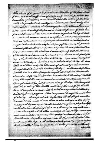
The claim of originality for the construction of the frame is not founded on the difference of shape only, but the peculiar combination of its parts, so as to withstand the action of the loom with the greatest advantage; without exterior bearings it is likewise founded on the economy of construction. As there are little more than half the pieces which the frame of other improved looms as the common loom requires, the lay or beater is made in the common manner, excepting a method of changing the shuttles, to place them near together for narrow cloth, or farther apart, as may suit the width of the warp, or the fancy of the weaver; the front side and end of the shuttle box are fastened together; the end of the shuttle box has one end of the shuttle rod secured firmly to it, the other end of the shuttle rod, is secured by a bend or iron screwed on the front of the lay. The shuttle box is fastened to the lay by a screw through its end, into the lay; having a nut at the back of the lay to screw it firm at that end; the other end is fastened by a screw driven through the side into the bottom of the lay. On the inside of the shuttle box is a steel spring, having its elastic point toward the closed end of the shuttle box and riveted to the side of the shuttle box; through the side a screw is inserted so as to press upon the spring & make it project from the side of the box; this spring is to stop the recoil of the shuttle on striking the end of the shuttle box; it may be covered with leather or any other substance suitable for the purpose. There is a groove through the under beam of the lay through which the picker blocks play (as in other looms). On the under beam there is also a long wooden spring made fast by one end, the other end having some play in a staple so that when the spring is pressed it will give way with ease until the staple at the other end stops its elasticity in some degree and renders its power greater; this spring is of use in throwing the shuttle as in the following manner. To throw the shuttle; the motion of the lay as it is thrown back gives the impelling force to the shuttle, & the change of the tickles gives the alternate direction
Page 4.
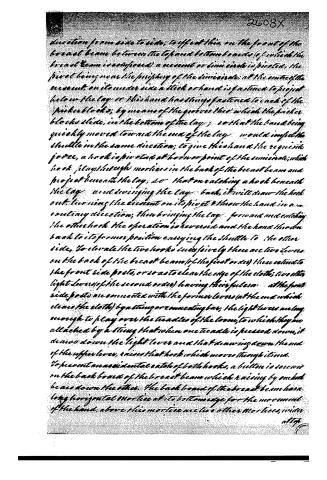
direction from side to side; to effect this on the front of the breast beam between the top and bottom ends (of which the breast beam is composed) a crescent or limacircle is pivoted, the pivot being near the periphery of the limacircle; at the centre of the crescent, on its under side a stick or hand is fastened to project below the lay or this hand has things fastened to each of the picker blocks; by means of the grooves thus which the picker blocks slide, in the bottom of the lay; so that the hand being quickly moved toward the end of the lay would impel the shuttle in the same direction; to give this hand the requisite force, a hook is pivoted at horn or point of the limacircle, which hook plays through mortices in the back of the breast beam and project beneath the lay, so that on catching a hook beneath the lay and swinging the lay back, it will draw the hook out, turning the crescent on its pivot & throw the hand in a contrary direction; then bringing the lay forward and catching the other hook the operation is reversed and the hand thrown back to its former position carrying the shuttle to the other side. To elevate the two hooks successively there are two levers on the back of the breast beam (of the first order) these extend to the front side posts, or so as to clear the edge of the cloth; two other light levers (of the second order) having their fulcra at the front side posts are connected with the former levers (at the end which clears the cloth) by a string or connecting bar; the light levers are long enough to play over the teadles of the loom, to which they are attached by a string that when one teadale is pressed down, it draws down the light lever and that drawing down the end of the upper lever, raises that hook which moves through it and. To prevent an accidental catch of both hooks, a button is secured on the back board of the breast beam which raising by one hook bears down the other. The back board of the breast beam has a long horizontal mortice at its bottom edge for the movement of the hand, above this mortice are two other mortices, wider
all of
Page 5.
at top than at bottom in which the two hooks move which are pivoted into the horns or points of the semicircle or segment and at which the spring which is fastened on the bottom of the box. This spring prevents a jerk or laterous impulse in acting on the hook to throw the shuttle. To wind the yarn on the yarn beam regularly I keep it more separate than is commonly done, the yarn beam is divided into a number of small divisions each division having a gutter or groove turned in the yarn beam; these grooves are to receive hoops of iron or tin, which are hinged together in two or three pieces so as to clasp round the yarn beam again to constitute thin separations in the warp; at where the hoops with a screw holds the circle together, which being taken out, the circle can be opened and removed from between the bodies of yarn which it separated; if three hoops are used, the two spaces are to be filled with warp, the middle hoop is then unhinged and removed to the next division where it being placed, that space between the two hoops is filled and the middle hoop removed to another division; the outside hoop remaining to keep up the yarn square on the beam. When the warp is as wide as the weaver desires here the last hoop is left to keep the selvage yarn regular. To take the loom with greater certainty of not losing a thread I have devised the following machine. Two narrow pieces of metal of a homogeneous nature (as brass, copper, steel, iron or tin) and with holes the size of a common knitting needle & about four times that distance asunder. These strips of metal are made fast in a frame horizontal and and parallel to each other and a few inches distance apart, so that the holes may be over each other, that wire may pass perpendicularly in them. Above these metal pieces & parallel to these, two wires are stretched, one on each side, wire jacks are then made by turning the end of a piece of wire to form an eye for the thread to pass through, the other end being cut long enough to reach from the other wires to a little below the under strip of metal. One of these is tied into each hole; a board is then made by inserting pins, or else cutting out
Page 6.
out not the distance of every other jack apart, which being fixed beneath the points of the jacks will raise every other one to receive the yarn of the warp, which is passed through from the spools over the two side wires, that the eye of the jack will be held suspended, until the thread breaks; when by the jacks falling on the metal strips, notice will be given of its failure. The eye readily detects which thread has broken. The board being then removed to press beneath the other half of the jacks, they are raised above the wires and the yarn passed through them; the two alternate blades are then united into a leak. This leaching machine being placed at the rear of the loom, the warp can be wound on the yarn beam without removing it from its place and the subdivisions of the yarn beam, with the metal hooks, a few spools will be sufficient to wrap any width of cloth. When the warp is wound on the yarn beam it is necessary, an exact quantity should be wound on every part; to ascertain this a tally wheel is applied at the side of the loom. At the end of the yarn beam a pin is driven to project a short distance; every revolution of the yarn beam moves one tooth of a small wheel above, by this pin entering its space, this wheel has a similar pin projecting some distance from its axis, which acts in a similar manner on another wheel placed above that one; if the pin on the axis of the yarn beam, moved a tooth of the tally wheel once in 3 feet and there were ten teeth in that wheel, it would of course revolve once in thirty feet or ten yards. This tally wheel having a similar eccentric pin or tooth to give motion to another tally wheel would give a tally of 100 yards, each of these tally wheels should have a spring or pawl to hold them firm without changing until the eccentric pin gives them motion. To wind up the cloth when it is woven a large roller or truck is turned on the end of the yarn beam, a small one on the end of the cloth beam; each of these rollers has several grooves for bands, the diameter of the grooves decreasing on one beam and increasing in the opposite roller of the other beam; round these rollers a band is put moving, beginning to weave with the band on the largest roller of the yarn beam and
Page 7.
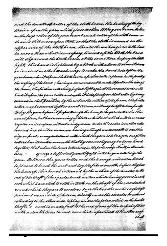
and the smallest roller of the cloth beam; the beating of the loom drives upon the yarn which gives motion to the yarn beam; but the on the large roller of the yarn beam & small roller of the cloth beam & drives still more upon that, so that the cloth is wound on the upper side of the cloth beam. Should the motion given to the band be more than what is necessary, to wind up the cloth, the band will slip round the cloth beam, at the same time keeping the cloth tight; this band is tightened by a block with a lever to draw it down as is usual in other machinery; to make the band hold tight on the yarn beam, when it slips on the cloth beam, a friction roller is placed in the front of the roping of the band; having a screw and nut to make it fast on the side of the loom; this friction roller being pressed tight against the screwed band; will bind it upon the yarn roller and make it hold firmly on that roller by being screwed in that position, by the nut on the outside of the frame; this friction roller may be screwed tight so as not to turn, or it may be left to turn freely to size the yarn before it passes through the hump; the yarn roller is in the usual place, but has a covering of cloth or knit web which will be even and regular on its surface without a ridge seam. Under this roller is another roller covered in a similar manner, having a trough underneath to contain size or paste or any substance with which the yarn is to be sized; one of these rollers has its center movable that by a screw they may be borne hard together; that when the lower roller is in the paste or size it will, in its rotation, squeeze a sufficient quantity of it into the yarn roller to size the yarn. Between the yarn roller and the hump a circular brush is placed to brush the web and lay the fibres smooth, before they pass the hump. This brush is turned by the motion of the treadle; on the end of the shaft of the circular brush are two wheels having grooves in each, each wheel has a click to catch in teeth on the shaft of the circular hub round which they are to revolve; over the treadle are two cross shafts pinioned on one side of the loom, directly under the circular brush and extending to the other side, to play under the false wheel on the hump's shaft; a cord is made fast to the end of one of the cross shafts with a double turn to one, one wheel is fastened to the other cross shaft
Page 8.
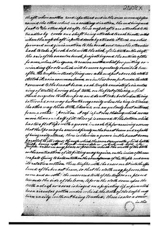
shaft, when another cord is fastened and in the same manner as for round the other wheel in a contrary direction, the end being made fast to the other top shaft, these top shafts are attached to the treadles by cords one shaft being attached to each treadle; when when the top shaft is pulled down by a treadle it turns one wheel forward and gives motion to the brush and turns the other wheel back to take a fresh hold with the slick, of the teeth on the shaft. The axis of the enamel brush, projects beyond the outside of the frame, when it is square, to receive another wheel for quilling or winding spools which will be more regularly described hereafter. The temples instead of being movable and put above the cloth to stretch it, as in common looms, are in this loom put under the cloth & secured to the breast beam. Each temple consists of a circular ring of metal, having sharp teeth, on the flat of the ring, which stand angular to its surface and do not take hold when the ring is turned one way but enter very easily when the ring is turned the other way; these teeth, likewise, are angularly bent outwards from a vertical position. A cap is put over the ring which covers more than one half of it; this cap is secured to the bottom, which has two flat lips with a groove in each lip, for receiving a screw, that the lips may be secured firmly on the breast beam and capable of being easily altered; there is likewise a groove in the breast beam, parallel to its edges; through which the same screws enter which hold the temples, having nuts or thumb screws below which will hold the temple-cases in any place or position which the width of the cloth or the contraction of its filling may require, on the inside of the case is a half spring to hold on teeth on the circumference of the temple and secure its rotative motion. These temples with the cases are let into the upper board of the breast beam, so that the cloth may pass over them even and smooth; the uncovered teeth of the temples are placed towards the side of the loom; to force the cloth down upon the teeth a clasp or cover is hinged on a projecting lip or piece which has a circular gutter under which the teeth of the temple may turn easily without being touched; there is also a screw in this
Page 9.
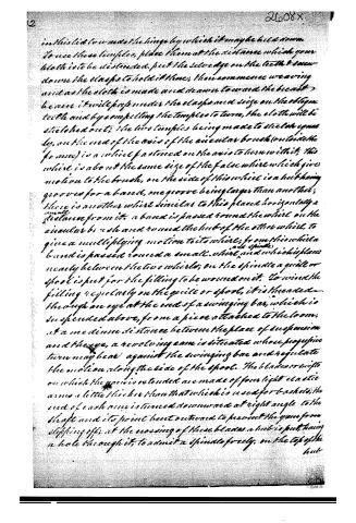
in this lid to prevent the hinge by which it may be held down. To use these temples, place them at the distance which your cloth is to be distended, put the selvage on the teeth & draw down the clasps to hold it there; then commence weaving and as the cloth is made and drawn toward the breast beam it will pass under the clasps and seize on the oblique teeth and by compelling the temples to turn, the cloth will be stretched out; the two temples being made to stretch equally, on the end of the axis of the circular brush (outside the frame) is a wheel fastened on the axis to turn with it; this wheel is about the same size of the false wheel which gives motion to the brush, on the side of this wheel is a hub having grooves for a band, one groove being larger than another; there is another wheel similar to this placed horizontally a small distance from it; a band is passed round the wheel on the circular brush and round the hub of the other wheel, to give a multiplying motion to its wheel; from this wheel a band is passed round a small wheel and spindle nearly between the two wheels; on the spindle a quill or spool is put for the filling to be wound on it. To wind the filling regularly on the quill or spool, it is threaded through an eye at the end of a swinging bar, which is suspended above, from a piece attached to the loom; at a medium distance between the place of suspension and the eye, a revolving cam is situated whose progressive turn may bear against the swinging bar and regulate the motion along the side of the spool. The blades or swifts on which the yarn is extended are made of four light elastic arms a little thicker than that which is used for baskets; the end of each arm is turned downward at right angle to the shaft and its point bent outward to prevent the yarn from slipping off; at the meeting of these blades a hub is put, having a hole through it, to admit a spindle freely, on the top of the hub
Page 10.
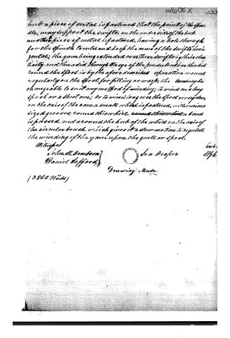
but a piece of metal is fastened that the point of the spindle, may support the swifts; on the underside of the hub another piece of metal is fastened, having a hole through, for the spindle to enter and keep the arms of the swifts horizontal; the yarn being extended over these swifts by their elasticity and threaded through the eye of the pendulous bar that is round the spout is by the afore described operation wound regularly on the spool, for filling or warp; the band may be changeable to suit any method of winding; to wind on a long spool or a short one; or to wind long over the spout or very slow on the axis of the cam a small wheel is fastened, with various sized grooves; round this wheel, round this wheel a band is passed and around the hub of the wheel on the axis of the circular brush, which gives it a slow motion to regulate the winding of the yarn upon the quill or spool.
Witnesses
John W. Dearborn
Daniel Stafford
Ira Draper
Drawing Made
(3850 Wicks)
About this record
- Patentee
- Jim Shaw's X-patent list
- Date
- the Name and Date index of patents, USPTO records, Jim Shaw's X-patent list
- Invention
- the Name and Date index of patents
- Listed in
- the Name and Date index of patents, USPTO records, Jim Shaw's X-patent list, S. A. Elliot's printed list of patents
- S. A. Elliot's printed list of patents gives the same name and date.