

Drawings and documents
USPTO scan
The patent as scanned by the USPTO
-
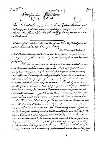 Page 1
-
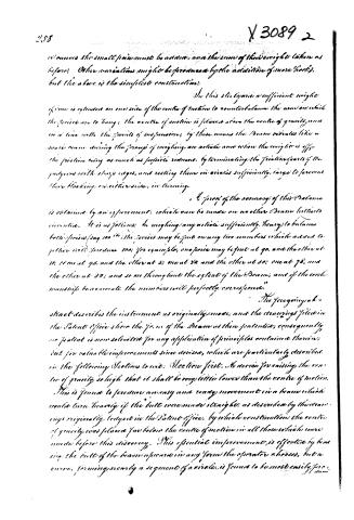 Page 2
-
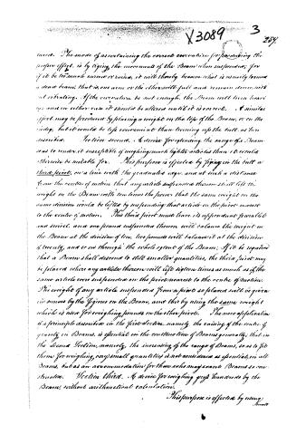 Page 3
-
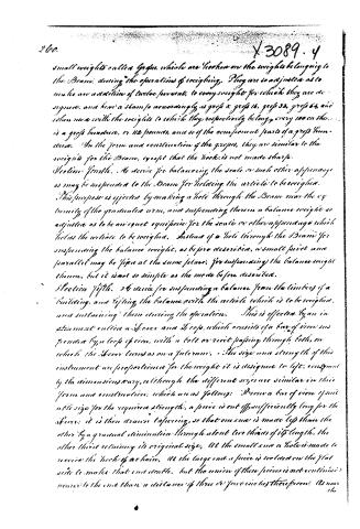 Page 4
-
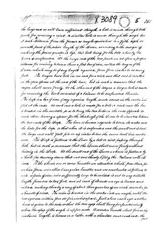 Page 5
-
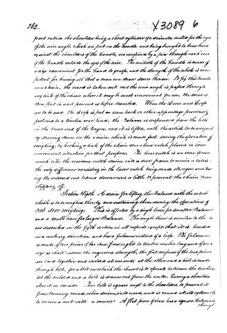 Page 6
-
 Page 7
-
 Page 8
-
 Page 9
-
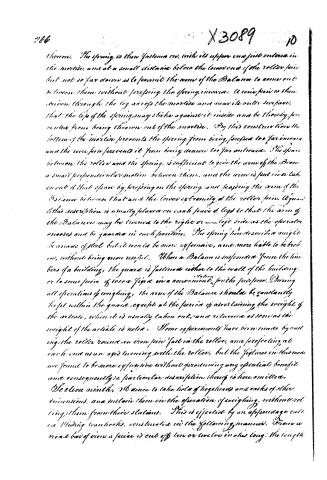 Page 10
-
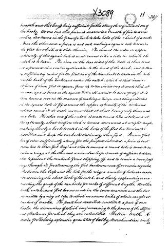 Page 11
-
 Page 12
-
 Page 13
-
 Page 14
-
 Page 15
-
 Page 16
-
 Page 17


U.S. Patent and Trademark Office · Google Patents
Show the transcription Hide (7,256 words)
Machine transcription (LightOnOCR) of the pages as scanned by the USPTO, most of them the handwritten copies made when the records were restored after the 1836 fire. Not checked; it can misread handwriting, so compare it with the scan.
Page 1.
X 3089
Mar. 24, 1819.
Benjamin Dearborn
Letters Patent
The Schedule referred to in these Letters Patent and making part of the same containing a description in the words of the said Benjamin Dearborn himself of his improvement on his Balance.
Abstract of the original specification of the Vibrating Steelyard or Just Balance, patented February 14, 1799.
The vibrating Steelyard or Just Balance is made partly of iron and partly of steel, of any dimensions requisite for weighing the smallest or largest articles from gold coins to hogsheads of Sugar &c.
The Beam is granulated on one edge with notches, on which two poises are hung, or one only, as occasion may require. The poises (or poises as they are usually termed) may be made of lead, iron, brass, or any other metal, or even of stone. If made of lead they should be guarded by a trap or other suitable case, to prevent a reduction of weight by wearing, and by those who use the instrument all its parts should be preserved from corrosion. This steelyard, when constructed of the most convenient size for family use, will weigh from one pound to two hundred and fifty, and one of the poises must weigh two pounds, and the other sixty-nine pounds, every notch on the Beam producing a variation of two ounces with the small poise and one pound with the large in the respective weight. The poises might be made of other sizes but these are the most convenient. The long arm of the beam is made sloping upwards to nearly a sharp edge, on which the notches are cut. On the two sloping sides are figures denoting the weights, one being marked for the small poise, and the other for the large, which must be added together when both poises are on. A steelyard of this construction, to weigh five hundred weight needs only to have its parts made stronger, and the large poise to weigh thirty-two, instead of sixty-nine pounds, doubling all the numbers on the large side of the Beam. The notches with the thirty-two pound poise will produce a variation of two pounds each, and to obtain single pounds
45
Page 2.
258
Y 3089 2
removes the small pairs must be added, and the sum of their weight taken as before. Other variations might be produced by the addition of more hooks, but the above is the simplest construction.
In this steelyard a sufficient weight of iron is extended on one side of the centre of motion to counterbalance the arm on which the species are to hang; the centre of motion is placed above the centre of gravity, and on a line with the points of suspension; by these means the beam rotates like a scale beam during the process of weighing an article and when the weight is off—the friction being as much as possible reduced, by terminating the friction parts of the pulleys with sharp edges, and resting them in circles sufficiently large to prevent their blocking, or either side, in turning.
A proof of the accuracy of this balance is obtained by an experiment, which can be made on no other Beam hitherto invented. It is as follows: In weighing any article sufficiently heavy to balance both species (say 100 lb) the species may be put on any two numbers which added together will produce 100; for example, one species may be put at 90, and the other at 10; or one at 95, and the other at 5; or one at 80, and the other at 20; or one at 78, and the other at 22; and so on throughout the extent of the Beam; and if the workmanship be accurate, the numbers will perfectly correspond.
The foregoing abstract describes the instrument as originally made, and the drawings filed in the Patent Office show the form of the Beam as then patented; consequently, our patent is now solicited for any application of principles contained therein, but for valuable improvements since devised, which are particularly described in the following Sections to wit: Section first. A device for raising the centre of gravity so high that it shall be completely lower than the centre of motion. This is found to produce an easy and ready movement in a beam which would turn heavily if the butt were made straight, as described by the drawings originally lodged in the Patent Office, by which construction the centre of gravity was placed far below the centre of motion in all those which were made before this discovery. This essential improvement is effected by bending the butt of the beam upwards in any form the operator chooses, but a curve, forming nearly a segment of a circle, is found to be most easily pro-
Page 3.
X 3089 3 257.
insect. The mode of ascertaining the correct curvature for producing the proper effect, is by trying the movement of the Beam when suspended; for if it be too much curved or raised, it will thereby become what is usually termed a dead beam, that is, one arm or the other will fall and remain down without vibrating. If the curvature be not enough, the Beam will then heave up; and in either case it should be altered until it is correct. A similar effect may be produced by placing a weight on the top of the Beam, or on the center, but it would be less convenient than turning up the butt, as here described.
Section second. A device for extending the range of a Beam so as to render it susceptible of weighing much lighter articles than it would otherwise be suitable for. This purpose is effected by fixing in the butt a third pivot, on a line with the graduated edge, and at such a distance from the centre of motion that any article suspended thereon shall lift the weight on the Beam with ten times the power that the same weight on the same division would be lifted by suspending that article on the pivot nearest to the centre of motion. This third pivot must have its appendant parallel and vertical, and one pound suspended thereon will balance the weight on the Beam at the division of ten, two pounds will balance it at the division of twenty, and so on through the whole extent of the Beam. If it be required that a Beam shall descend to still smaller quantities, the third pivot may be placed where any article thereon will lift sixteen times as much as if the same article were suspended on the pivot nearest to the centre of motion. The weight of any article suspended from a pivot so placed will be given in ounces by the figures on the Beam, and this by using the same weight which is used for weighing pounds on the other pivots. The new application of a principle described in the first section, namely, the raising of the centre of gravity in Beams, is essential in the construction of Beams generally; that in the Second Section, namely, the increasing of the range of Beams, so as to fit them for weighing very small quantities is not considered as essential in all Beams, but as an recommendation for those who may want Beams so constructed.
Section third. A device for weighing gross hundreds by the Beam, without arithmetical calculation.
This purpose is effected by using
Page 4.
260.
small weights called Gross, which are hooked on the weights belonging to the Beam; during the operations of weighing. They are so adjusted as to make an addition of twelve per cent, to every weight for which they are designed, and have a stem so accordingly, as gross 8, gross 16, gross 32, gross 64, and when used with the weights to which they respectively belong, every 100 on the is a gross hundred, or 112 pounds, and so of the component parts of a gross hundred. In the form and construction of the gross, they are similar to the weights for the Beam, except that the hook is not made sharp.
Section Fourth. A device for balancing the scale or such other apparatus as may be suspended to the Beam for holding the article to be weighed. This purpose is effected by making a hole through the Beam near the extremity of the graduated arm, and suspending therein a balance weight so adjusted as to be an equal equipoise for the scale or other apparatus which holds the article to be weighed. Instead of a hole through the Beam for suspending the balance weight, as before described, a small pivot and parallel may be fixed at the same place, for suspending the balance weight thereon, but it is not so simple as the mode before described.
Section Fifth. A device for suspending a balance from the timbers of a building, and lifting the balance with the article which is to be weighed, and sustaining them during the operation. This is effected by an instrument called a Screw and Gross, which consists of a bar of iron suspended by a loop of iron, with a bolt or nut passing through both, on which the Screw turns as on a fulcrum. The size and strength of this instrument are proportioned for the weight it is designed to lift, according to the dimensions vary, although the different sizes are similar in their form and construction, which are as follows: From a bar of iron of suitable size for the required strength, a piece is cut off sufficiently long for the Screw; it is then drawn tapering, so that one end is made less than the other by a gradual diminution through about two thirds of its length, the other third retaining its original size. At the small end a hole is made to receive the hook of a chain, at the large end a piece is bolted on the flat side to make that end double, but the union of these pieces is not continued nearer to the end than a distance of three or four inches therefrom. As near the
Page 5.
the large end as will leave sufficient strength, a hole is made through both parts for receiving a rivet. A similar hole is made through the single bar at such distance from the former as may be equivalent to a fifth, sixth, or seventh part of the whole length of the lever, according to the design of making the power greater or less, this hole being for the bolt whereby the lever is suspended. At the large end of the two parts are set upon a proper distance for receiving between them a flat bar of iron, called the tongue of the lever, which may be of any length required, from four inches to as many feet. The tongue has a hole in one end for a rivet, and that end is riveted in the open space at the end of the lever, but in such a manner that the tongue shall move freely. At the other end of the tongue a larger hole is made for receiving the hook or screw of a balance to be suspended therein.
The loop is a bar of iron of any required length, made round in the centre and flat at the ends. At each end a hole is made for a bolt or rivet, and the bar is bent in the middle, so as to bring the two holes in the ends opposite to each other, leaving a space for the thickness of the lever to be inserted between the two ends of the loop. The lever is bent at an angle between its centre and the hole for the loop, so that when it is suspended and the small end is bent, the large end will fall five or six inches below the same level line continued. The loop is fastened to the lever by a bolt or rivet passing through both, but in such a manner that the lever shall move freely without binding in the loop. At the small end of the lever a chain is fastened by a hook for drawing down that end and thereby lifting the balance with its load. To the chain one or more handles are attached which from their peculiar form, are called triangular handles, and are constructed as follows, to wit, a piece of iron wire sufficiently large to be riveted is cut to any suitable length from one to two feet, and at each of its ends an eye is turned and riveted, making thereby a ring of about three quarters of an inch diameter for a handle of wood. The wire is bent in the centre into an angle, until the two eyes are within four or five inches apart. Just above each eye another bend is given to the wire so that the two eyes shall hang perpendicularly when the apex of the angle is uppermost. A wooden handle about five or six inches in length is turned in a lathe, with a shoulder near each end, the part
Page 6.
262.
X3089 6
part outside the shoulder being a short cylinder of a diameter suited for the eyes of the wire angle, which are put on the handle, and being brought to bear hard against the shoulders of the handle, are confined by a pin through each one of the handle outside the eyes of the wire. The middle of the handle is made of a size convenient for the hand to grasp, and the strength of the whole is competent for bearing all that a man can draw down thereon. To fix this handle on a chain, the screw is taken out, and the wire angle is passed through any link of the chain where it may be most convenient for use, the screw is then put in and secured as before described. When the Screw and Scope are to be used, the Scope is put on some hook or other appendage previously fastened to a timber over head; the Balance is suspended from the hole in the lower end of the tongue, and it is lifted, with the article to be weighed, by drawing down on the chain, which is made fast, during the operation of weighing, by hooking a link of the chain over a lever catch placed in some convenient situation for that purpose. The lever catch is an iron forme much like the common catch driven into a door frame to receive a latch: the only difference consisting in the lever catch being made stronger, and having the outward end turned downward a little to prevent the chain from slipping off.
Steeling Sight. A device for lifting the Balance with the article which is to be weighed thereby, and sustaining them during the operations of our door weighings. This is effected by a single lever for smaller Balances and a double lever for larger Balances. The single lever is similar to the lever described in the fifth section in all respects except that it is bent in a contrary direction, and has a fulcrum instead of a loop. The fulcrum is made of two pieces of bar iron, from eight to twelve inches long and of such size as shall ensure the required strength; the flat surfaces of the two pieces are laid together and welded at one end; at the other end a hole is made through both, for a bolt on which the lever is to operate between the two bars. At the welded end a hole is drawn out from the center, having a shoulder above it on one side. This hole is square next to the shoulder, to prevent it from running round, when driven into wood, and is round at its extremity to receive a nut with a screw. A flat piece of iron has a square hole made through
Page 7.
through it, to fit the square part of the bolt, and is put thereon to prevent the shoulders of the fulcrum from sinking into the wood. The fulcrum is secured to the head-piece of the frame as described in section seventh, by driving the bolt through a hole in the head-piece and screwing on a nut. This lever is accompanied with a chains-handle, and lever-catch, as described in section fifth, and its tongue passes through a mortise in the head-piece of the frame, the lever-catch being driven into a nail placed in the frame for that purpose, and to unite the parts of the frame, and keep them from spreading. The movable lever consists of two single levers with their fulcrums, chains-handles, and lever-catches, similar to the preceding description, except that one of them has two tongues, and the other one, the three tongues passing through a mortise in the head-piece, are united by a bolt under the head-piece, to which bolt a loop is attached for sustaining the Beam when suspended and for lifting it with the articles to be weighed, by removing on both levers which are placed in opposite directions.
Section seventh. A device for supporting the Balance and its apparatus in operations of out-door weighing, and to constitute the, as to be easily moved about, without being separated or taken down. This is effected by an instrument called a Frame, consisting of two pairs of legs and a head-piece, constructed in the following manner: From a plank of hard wood such as Oak, of suitable thickness, two strips are sawed of such length and breadth as the intended Frame may require. These two pieces are united together in an angular position, that is, they are brought close together at one end, and separated at the other end a sufficient distance to make the frame stand firmly when set up. They are secured to each other by one or more rails or cross bars with tenons and pins in the open parts, and a piece in the form of a wedge bolted between them near the moving end. The wedge is not brought to a sharp point, but is left about an inch thick at its smallest end, to take part of the bearing of the head-piece, the other part of the bearing being placed on two shoulder-irons made just even with the end of the wedge in the two pieces which are partly cut away above the wedge so as to produce a parallel opening similar to the sides of a mortise, for receiving the ends of the head-piece therein another
Page 8.
another pair of legs, being made in the same manner, one pair supports one end of the head-piece, and the other pair supports the other end constituting four bearings or feet, on which the whole mechanism is supported when in use, and the ends of the rails run through the legs a sufficient distance to constitute freedom for lifting the frame and balance. The frame piece is a piece of timber (generally Oak) of suitable dimensions for the frame intended to be made. Its thickness is usually about double the space in the parallel opening above mentioned and its breadth about a quarter more than its thickness. On the two broad sides a piece is taken out near each end, making thereby four spaces, each of which is of a depth equivalent to about a quarter of the thickness of the frame piece, and of a length sufficient to receive the tops of the legs, with a wedge to secure it. A neck is then formed near each end of the head-piece, to fall into the parallel opening of the legs and be fastened by wedges. From this description it will be seen that the neck is about half the thickness of the timber, and each neck must be a sufficient distance from the ends of the head-piece to have substance outside the neck for driving the wedges without danger of splitting off the parts against which they bear. The outer shoulders of each neck are usually made a little tapering or dovetailing inward to prevent the wedges from working out, and the legs are so set as to spread a little wider below than at top. Four wedges are made to fit the spaces here described and thereby bind the parts firmly together, and to prevent the wedges from being lost they are fastened by short chains at the different quarters where they belong. In the centre of the head-piece a mortise is made through it for the tongue of the single lever or the three tongues of the double lever, and these tongues are always so long as to reach a little below the lower surface of the head-piece when the small end of the lever is down. The bolt of each fulcrum is driven through a hole in the head-piece, and is secured by a nut below and the lever catch is fixed on the rail or cross bar before mentioned.
Hood or shield. A device to confine the graduated arm of the balance in its proper station when mounted and thereby guard it from the injurious results of a sudden impulse. This is effected by an apparatus called a guard constructed in the following manner: A roller from two to four
Page 9.
two inches long, and from one to three inches diameter, is made of an iron, brass, or copper temper, with a little point, which is sometimes best and is cut with a hole in its centre to turn on a pin. It may be cylindrical in the whole length, or partly so in the centre with a projecting flange at each end, and the hole through it must be sufficiently large to receive an iron pin of competent strength for the greatest pressure with which the balance can operate thereon when loaded with its utmost quantity. The pin is made from a round rod, as large as the hole in the roller will admit to turn freely thereon, it is cut from six to twelve inches long, according to the pressure required, and at one end it is drawn square and sharp pointed to drive into the roller, the remainder of its length being round. Near the centre of its length it is turned at a right angle, or very nearly so, the sharp point end is then passed through the roller and at a suitable height for the arm of the balance is driven into one of the legs of the frame as far as the length of the roller will permit without confinement. The other end of the pin is turned downwards and projects some inches below the roller, making there by a space between the pin and the frame, for the graduated arm of the balance to be confined in under the roller. To guard the balance from being accidentally thrown out of this space, a spring is placed below it constructed as follows. From a round iron rod similar to the pin before described, a piece is cut from one to two feet long, according to the length of the spring required. One half of its length, or a little more, is drawn flat to a thin substance and has two or more holes made therein for nails or screws, it is of laminated hammered steel to give it the necessary elasticity for a spring, near the other end it is bent into a right angle, making there by a short lip about half an inch long. It is then bent into such a form that the spring when finished very much resembles the figure 7, the longest line of the figure representing the elastic part of the spring, at the lower extremity of which it is fastened by screws or nails to the leg of the frame. Having to the spring being put on, a mortise is made in the leg of the frame, a small distance below the end of the roller pin which extends downwards below the roller. This mortise is cut nearly through the leg, and is just large enough for the upper part, or horizontal line of the spring with its lip to move freely therein.
Page 10.
thereon. The spring is then fastened on, with its upper end just entered in the mortise, and at a small distance below the lower end of the roller pin, but not so far down as to permit the arm of the Balance to come out between them without pressing the spring inward. A cone pin is then driven through the top across the mortise and near its outer surface, that the top of the spring may strike against it inside and be thereby prevented from being thrown out of the mortise. By this construction the bottom of the mortise prevents the spring from being pressed too far inward and the cone pin prevents it from being thrown too far outward. The space between the roller and the spring is sufficient to give the arm of the Beam a small perpendicular motion between them, and the arm is put in a lock out of that space by pressing on the spring and passing the arm of the Balance between that and the lower extremity of the roller pin. Again, if this description is usually placed on each side of legs so that the arm of the Balance may be turned to the right or left side as the operator chooses and be guarded in each position. The spring here described might be made of steel but it would be more expensive, and more liable to be broken, without being more useful. When a Balance is suspended from the timbers of a building, the guard is fastened either to the wall of the building, or to some piece of wood fixed in a convenient place for the purpose. During all operations of weighing, the arm of the Balance should be constantly kept within the guard, except at the period of ascertaining the weight of the article, when it is usually taken out and returned as soon as the weight of the article is noted. Some experiments have been made by cutting the roller round an iron pin fast in the roller, and projecting at each end as an arm turning with the roller, but the fixtures in this mode are found to be more expensive without producing any essential benefit and consequently no particular description thereof is here omitted.
Section ninth. To secure to take hold of hogsheads and casks of other dimensions, and sustain them in the operation of weighing, without removing them from their stations. This is effected by an apparatus called a sliding manhook, constructed in the following manner. From a round bar of iron a piece is cut off ten or twelve inches long; the length
Page 11.
breadth and this being sufficient for the strength required in one of the hooks. At one end this piece is drawn to a breadth of five to seven inches, and turned in the form of a hook to take hold of the chain of a cask. Near the other end a piece is cut out, making a square hole to receive the flat bar which is to slide therein. The iron at the outer or upper extremity of this square hole is made round like a bolt, on which the catch is to turn. The iron on the two sides of the hole is then turned upwards in a contrary direction to the bend of the hook, and is thus sufficiently raised for the flat bar of the can hooks to slide in the hole over the back of the hook, and under the catch, which is thus formed:
A piece of iron, flat or square, from six to ten inches long is made thin at one end, and as broad as the square hole will admit to move freely; it is then turned over in the manner of making a hinge, and being inserted in the square hole is fixed round the upper extremity of the hook and rolled round it in such a manner that it shall turn freely thereon as on a bolt. The other end of the catch is made round like a bolt, and at the extremity, about half an inch is turned downwards at a right angle, making thereby a hook to catch in the hole of the flat bar herein described, and keep the can hooks stationary, where fixed. From a flat bar of iron sufficiently strong for the purpose intended, a piece is cut from five to three feet long, and close to one end a round hole is made to receive a ring; at the other end a circular loop is made of sufficient diameter to prevent the can hooks from slipping off, and to receive a loop passing through it, for straining the flat bar downwards if occasion requires. Between the loop and the hole for the ring, a number of holes are made, for receiving the short hooks of the catch, and thereby expanding or contracting the grasp of the can hooks for casks of different lengths. Another hook, catch, and flat bar are made in the same manner, and the two are united by a ring at top, to which one or more lengths of chain may be attached if wanted. The parts here described constitute a pair of can hooks, the dimensions of which vary according to the powers of the different Balances for which they are calculated. Section: length: 6 inches for holding extensive quantities of bulky merchandise, such as
Page 12.
268
X 3089 12
as hampers, bags of coffee or spices &c are sustaining them in the operation of weighing.
The instrument for this purpose is called a Policing Scale and is constructed in the following manner. Two similar pieces of oak or other strong wood are prepared for the two sides of the scale, the dimensions of each being as follows viz. length about seven feet six inches, breadth four inches, thickness three inches. They are placed parallel to each other, with the narrow surface upwards, at a distance of about twenty inches in the case between them, and are fastened to each other by six iron bars of iron, two of which have are rivetted on the upper surface of the sides at a distance of ten inches from their ends; two others are rivetted on the under surface of the sides at a distance of ten inches from their ends. These four iron bars are just as long as the breadth of the scale from out to out, that is, about twenty six inches in length. The two remaining bars are made so long, as to be turned up at a right angle at each end of each bar as high as the extremity of the sides, and to leave a space between the ends of the bars so turned up, and the outside of the sides, of about three quarters of an inch on each side; consequently the clear space in each bar between the parts so turned up at the ends, is about an inch and a half more than the breadth of the scale from out to out. These two bars are rivetted to the under surface of the sides six inches apart, each being three inches from the centre of the length of the sides. In each of the four ends turned up a hole is made to receive a wire or belt, passing horizontally through the iron into the sides, by which the scale with its case is to be suspended. These six iron bars may be about an inch and a half broad, and they must all be perforated with as many holes as are required for the before mentioned wires or belts; the four bars which are under the sides, must also have as many other holes as shall be requisite for rivetting upon them a flooring of boards. An iron loop is attached to each end of the scale, in such a manner as that they may turn inwards, and lie flat on the bottom of the scale, or turn outwards to an angle of about forty five degrees and be firmly supported in that position. These loops are similar to each other in form and size, being made in the following manner: A bar of iron about eight feet long, has a hole made about four inches distance from each end for a wire of proper strength. It is then bent in the centre
Page 13.
centre of its length into a semicircle, the diameter of which is nearly equal to the distance between the sills inside; the other parts of the bar remain straight, and constitute two parallel legs, one of which is rivetted inside each of the sills midway between the two bars rivetted near the ends thereof. On these two rivets the loops turn, and when thrown outwards, the extreme ends of the two legs bear against the lower bar, and at the same time the legs come to a bearing also against the upper bar, whereby the loops is sustained in the angular position before described, for supporting a weight to be loaded thereon when in use. When out of use each loop is turned down on the floor of the scale between the sills. This scale is suspended to the Balance by a forked iron, made in the following manner: a bar of suitable strength from an inch and a half to two inches wide, is cut to a length of three or four feet; one end is split in the centre of the width for about a foot in length; the two parts are opened into a fork, each part having a hole near the end to receive a bolt or rivet. This fork is opened so as to bring the distance of the two holes equal to the distance of the holes in the ends of the two bars rivetted under the scale, nearest its centre. One of these forked pieces is made for each side, and above the forks both are bent so that they may meet at top where they are rivetted together. At this union another piece is welded on having at the other end an eye, with two or three holes therein, for being suspended thereby to the Balance at any convenient height over the ground. The two forks are put into the spaces between the outside of the sills and the iron bars turning up, as before mentioned. A rivet on each side fastens the forked iron to the sills and on this rivet that iron turns so as to be laid flat on the scale and be packed in small compass. When the scale is to be used, that iron is turned up into a perpendicular situation and two bolts are put into the other two holes of the forks, whereby the suspending iron is made firm in its position. The two bolts are fastened to their respective stations by short chains, to prevent their being lost. Flooring of boards being rivetted on the four iron bars which are fastened under the sills, makes a close bottom to the scale, and the two loops when turned out, increase its length, so as to embrace an extent of eleven or twelve feet. Some of these folding scales have been formed with wooden tongues at the end instead of iron loops, but they were not so convenient, and are therefore
Page 14.
therefore not here described. Section eleventh. A device for holding bales of Cotton and sustaining them while weighing. This instrument is called Cotton-hooks, and is made in the following manner: A bar of iron about an inch square, is cut to a length from seven to nine feet, according to the length of the hooks intended. Each end is flattened out to a breadth of about two inches at the extremity, forming thereby, two tapering palms, and the centre of the bar is made round like a bolt, say eight inches in length. In this round part the bar is bent, so as to bring the two palms together edge to edge, leaving a loop at the bend to receive a ring. The two parts are then bent together into a suitable curve for receiving a bale of cotton, after which they are spread apart to a distance of about two feet and a half at the palms, but still remain close together, at the part next below the loop. Two bars thus formed into hooks, are secured together by a ring, which is in the loop of both so that the curves of the two shall be in opposite directions, to embrace a bale round and under such part thereof, as shall be competent for holding it to be weighed. When greater length is required, it is produced by including one or more links of chain in the ring.
Section twelfth. A device for holding bales of Sugar or other articles, and sustaining while weighing. This instrument is called a Standing Scale, and is made in the following manner: a bar of iron of about five feet long, two inches wide, and of proportionate thickness, is bent at one end, at about two feet from one end, so as to form a right angle. This bend is not turned to a sharp corner, but in a short curve, which is least liable to crack in working, and strongest when finished. Another bar of similar dimensions is turned in the same manner. In the shorter leg of each, two holes are made for rivets, one near the bend, and the other near the extremity; these holes are alike in each, so that when the two angles are placed side by side, the holes are opposite each other. Just above the turn of the angle each of the longer legs is bent a flat iron in opposite directions, so that when the two short legs are placed on a plane, with their sides perpendicular, and parallel to each other at a distance of about two feet apart, the tops or extremities of the two longer legs shall meet and be welded together, to this union another bar is welded to the two united angles, which is of the following form: From a
Page 15.
X3089 15 271
a bar somewhat larger than that above described, a piece is cut about three feet long, and an eye or loop of two or three inches diameter, is formed at one end, for suspending the scale thereby to the Balance. At about a foot distance from the loop, the bar is bent as before, in the manner above described, so as to form a right angle, and the end of the longer leg is inclined to the other angles at their union. To constitute a base for the flooring of the scale, two other bars are formed and fastened in the following manner: From a bar which may be somewhat less than either of the foregoing, a piece is cut about three inches longer than the clear space between the two short legs of the first mentioned angles. Close to each end of this bar a hole is made of the same size as the holes in those short legs, these holes are made for riveting the bar to those legs, and four other holes are made between them at proper distances, for riveting the wooden flooring to the iron. Each end of the bar is then turned up about an inch and a half, and the bar being placed between the short legs, is riveted to them at the holes nearest to the bend in the legs. Another bar is formed in the same manner to be riveted to the short legs at their outer ends, symmetrically. At the centre of this bar a small piece of iron is riveted for attaching a chain to the front of the Scale for sustaining a heavy load. This piece is from three to four inches long, having near one end a hole for a rivet, and at the other an eye or loop for receiving the hook of a chain; between these it is turned at a right angle, and when riveted on the bar the eye is upward, the loop of it being about even with the surface of the wooden bottom, to be now described. Upon the two bars last described a wood or bottom is fastened by rivets; the bottom may be of hard wood or pine, and from an inch and half to two inches thick. The scale thus formed has competent strength for sustaining the common bags of Havana or Sugar or any other articles not exceeding from one to two hundred pounds, but when it is used for heavier drafts, the chain becomes necessary for supporting the front of the scale. For this purpose a chain with a hook at each end, is provided, one of the hooks being put in the eye at the front of the scale, the other is passed through the loop above, through which the chain is drawn tight, and the hook at its end is curved downward, at a catch into any link where it will keep the chain in that position. The foregoing completes the
Page 16.
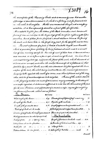
the description of the Steaming Scale as it is commonly used, but another appendage is sometimes added to it which is a folding seat for persons to sit on who wish to be weighed. As this is a convenient though not a necessary addition, it is here separately described as part of the specification.
At a suitable height from the bottom of the Scale to make a seat, two small pieces of iron are rivetted to the longer legs of the two first right angles before described, each of these pieces projects a small distance towards the front of the scale and has a hole in the projecting part, for the axis of the seat to turn in. The seat is formed of a piece of board of suitable length, and because which is guarded from splitting, by being fastened at each end to a small bar of iron running across it; one end of each of these bars is turned outwards and rounded, so as to form a pin or axis at each end of the seat. The iron studs are constituting two legs, supports the front of the seat, which stands at so turns on an axis, and when the seat is turned up it is fastened in that position by a small hook, and the iron standard lies flat against the lower surface of the seat, the whole being constructed in the manner of a common hanging table against the wall of a room, and thus is placed out of the way, when articles of merchandise are to be weighed. As some of the articles described in the foregoing sections are made of dimensions, varying according to the strength and scope required, it is deemed sufficient to add here the dimensions of the parts of a Steamer Balance, and apparatus of a medium size, say one for weighing one thousand pounds, which are as follows:
The Beam
<table>
<thead>
<tr>
…
Page 17.
X 3089 17 2/3.
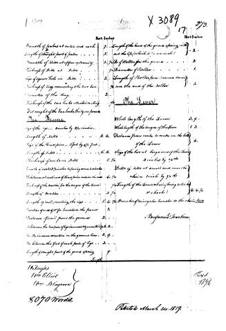
<table>
<thead>
<tr>
…
About this record
- Patentee
- DATAMP
- Date
- the Name and Date index of patents, DATAMP, USPTO records
- Invention
- DATAMP
- Listed in
- the Name and Date index of patents, DATAMP, USPTO records, Jim Shaw's X-patent list, S. A. Elliot's printed list of patents, Burke's List of Patents (1847)
- S. A. Elliot's printed list of patents gives the same name and date.
- Burke's 1847 Patent Office list gives the same patent.