

Drawings and documents
USPTO scan
The patent as scanned by the USPTO
-
 Page 1
-
 Page 2
-
 Page 3
-
 Page 4
-
 Page 5
-
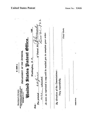 Page 6


U.S. Patent and Trademark Office · Google Patents
Show the transcription Hide (1,293 words)
Machine transcription (LightOnOCR) of the pages as scanned by the USPTO, most of them the handwritten copies made when the records were restored after the 1836 fire. Not checked; it can misread handwriting, so compare it with the scan.
Page 2.
United States Patent
Patent No.: X3626
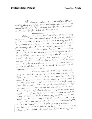
The Schedule referred to in this Letters Patent and making part of the same containing a description in the words of the said Rufus Grandy himself of his improvement in the saw set, for setting the teeth of saws.
Prepare made of iron, or of any other suitable material, a square or other convenient shaped straight bar, having one of its extremities drawn or shaped to a tapering point, for the purpose of receiving a handle. Let such handle be fixed permanently upon it. Let the length of such part of the said square, or other shaped bar, as appears or shows itself, outside of the handle aforesaid be equal to five or six inches more or less, as may be found most convenient. The thickness of the bar aforesaid may be from one fourth of an inch or less to half an inch, or more, according to circumstances; a large and strong saw requiring a thickness of material greater than what will be sufficient for a small one.
Imagine, now that this square or other shaped straight bar, as aforesaid, is laid on the table before you, that the handle of the same points directly towards you, and that the bar itself, of course, points directly from you. It must two and a half inches from the nearest extremity of the bar, but more or less as convenience requires, let the bar aforesaid be bent towards your left hand, for instance, or towards your right if you prefer it) in manner such as that the part of the bar so bent towards your left (or to the right as the case may be) shall make a right-angled angle with the former direction of the same part of the said bar, equal to twenty-five degrees of a circle, more or less, as may be found to be most convenient to the purpose to which the said saw set is to be applied.
Page 3.
United States Patent
Patent No.: X3626
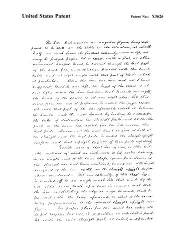
The bar, bent now in an angular figure, being supposed to be still on the table in the situation; at about half an inch from its farthest extremity, more or less, as may be judged proper, let a screw, with a flat, or other convenient shaped head, be carried through the bent part of the said bar, in a direction parallel with the said table, and at right angles with that part of the bar which it penetrates. When the bar has been bent, as I have supposed, towards our left, the head of the screw is at our left; when the bar has been bent towards our right, the head of the screw is at our right also. Let this screw, from the use it performs, be called the upper-screw. Let also, that part of the bar aforesaid, which is between the hands, and the angle formed by bending, be called, for the sake of distinction, the straight parts, and let the other part of the same bar called, for the like reason, the bent parts. Thereupon let the said hand engage or both of the straight and the bent parts, so called the straight upright surfaces and bent upright surfaces of those parts respectively.
Provide now a short bar of iron, or other suitable material of about an inch, more or less, as the case may be, in length and of the same shape, square for instance, as the straight bar just herein mentioned, having one of its longest edges of the same width as the straight upright surface herein mentioned. Let one extremity of this short bar, be inverted off to an angle, much like that made by the two sides of the tooth of a saw, in manner such that the line constituting the edge or angle so made, shall be parallel with the table aforesaid, or what is the same thing, perpendicular to the aforesaid straight, upright, surfaces. The proper place for this short bar, when use is put together for use, is a position in which it is parallel with the said straight part, so called, and parallel
Page 4.
United States Patent
Patent No.: X3626
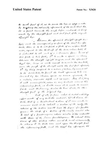
to such part of it, as to cause the line or edge made by bending the extremity aforesaid, of the said short bar, to a point towards the angle before mentioned as being made by the straight part and bent part of the original straight bar.
Between the aforesaid straight upright surfaces; and the corresponding surface of the short bar aforesaid, there is to be interposed, a plate of an uniform thickness, equal to the thickness of the bars, whose length it is intended to set and of a rectangular form. The use of this plate is two fold; 1st to make a space or cavity between the straight upright surfaces, and the aforesaid short bar, large or wide enough to receive the saw teeth, near the angle of the straight with the bent part aforesaid; 2nd by being confined to a certain position, by means yet to be described, to permit the teeth aforesaid, to be carried by the chains, space or excess aforesaid, to a certain, ascertainable depth, and no more. Thus it is plain, it will accomplish, when by any suitable means this intervening plate, as I will name it, is made to remain fixed and stationary, during its time of use, to the straight part of the original bar.
Last of all, suppose what is called a sliding collar made of any suitable material. Let its figure be such, that if a longitudinal section of it were made, in manner such as to exhibit a section of its cavity, the exterior of the section would have the figure of a parallelogram; the shape of a section of the cavity would also be that of a parallelogram whose similar sides are parallel with those of the former parallelogram. The internal dimensions of this sliding collar would be such as conveniently, to allow it to slide over and upon the straight part the intervening plate, and the short bar aforesaid. Let
Page 5.
United States Patent
Patent No.: X3626
this collar than, be so clicked over the parts just mentioned, while the machine we are describing is lying on the table before us. The open set is now in a condition fit for use, with the exception of a solitary screw. Enter then, this screw through the right hand end of the collar, as it lays before us, and use this screw which we may call the engaging screw, in such a manner as to press, when they are in their proper positions, the short bar, and the intervening plates, upon the aforesaid straight part of the bar first herein mentioned. The gear screw being now screwed or screwed into the bar as far as may be desirable, in order to bind the teeth into the respective slots, with the face of the screw, the bar, etc. is ready for use.
Witness
Thomas Skidmore
Harris Clough
Nigius Grandy
Ex.
9716.
(Filed Dec. 21st 1872)
Page 6.
United States Patent
Patent No.: X3626
DRAFTSMAN'S DIVISION.
All communications should be addressed to
"The Commissioner of Patents,
Washington, D. C."
2-328 a.
DEPARTMENT OF THE INTERIOR,
United States Patent Office.
Washington, D. C., 189--
SIR:
The printed copies of Patent No. 189--
are exhausted.
As soon as reprinted a copy will be mailed you to complete your order.
By direction of the Commissioner:
Very respectfully,
Chief Clerk.
31496-97-5m
About this record
- Patentee
- DATAMP
- Date
- the Name and Date index of patents, DATAMP, USPTO records
- Invention
- DATAMP
- Listed in
- the Name and Date index of patents, DATAMP, USPTO records, Jim Shaw's X-patent list, S. A. Elliot's printed list of patents, Burke's List of Patents (1847)
- S. A. Elliot's printed list of patents gives the same name and date.
- Burke's 1847 Patent Office list gives the same patent.