

Drawings and documents
USPTO scan
The patent as scanned by the USPTO
-
 Page 1
-
 Page 2
-
 Page 3
-
 Page 4
-
 Page 5
-
 Page 6
-
 Page 7
-
 Page 8


U.S. Patent and Trademark Office · Google Patents
Show the transcription Hide (2,396 words)
Machine transcription (LightOnOCR) of the pages as scanned by the USPTO, most of them the handwritten copies made when the records were restored after the 1836 fire. Not checked; it can misread handwriting, so compare it with the scan.
Page 2.
United States Patent
Patent No.: X3668
William M. Dodge
Letters Patent
The substance referred to in these Letters Patent and making part of the same containing a description in the words of the said William M. Dodge himself of his improvements in the art of printing.
His improvement consists in the construction and use of types and apparatus for printing.
These types are in some respects similar to those in common use; but the mode of producing the pressure is by means of rollers acting in socket or in inclined planes as instituted for the same. The rollers are elliptic or conical according to the construction of the apparatus. The press requires but the sections may be either circular sections or either of the above figures retaining the same of the two opposite sides of said figures or have the two opposite sides against which the pressure is exerted either cylindrical or circular and fitted into sockets or cavities of a corresponding shape; and while one of these cavities is stationary the other or others of them must be movable so that when a lateral motion is given it changes the pressure in a distance between the two cavities that is, when applied to the press any press, it allows the movable cavity to rise or fall by the motion of the bar. Thus suppose a cylindrical cavity to be made on the top of the platter and another to be made directly on it in the middle of the head of the press, and two of the above named sections fitted into these cavities while the opposite sides of the sections come in contact. When the platter is pressed sufficiently hard upon the type or press, the sections are drawn nearly by a perpendicular direction and their sides which come in contact are to each other by means of a conical cavity in the lower one and a hemispherical projection in the upper one. At the part the bar is connected by a link so that when it is pulled forward the platter is forced down upon the type the bar
Page 3.
United States Patent
Patent No.: X3668
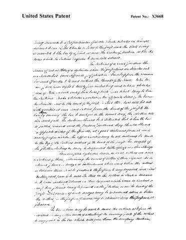
being secured to a perpendicular spindle which vibrates on hinges secured to one of the cheeks or sides of the prop, and the link being connected to the bar by a joint as near the centre of motion as the dimensions which the latter requires to move will permit.
The sections of a cone produce the same effect as those of a cylinder when the proportions are similar but are somewhat more difficult of application. Thus suppose the common bar and spindle to be used without the threads of the screw. Take two bars of iron from eight to thirty-five inches long and make a globular piece of steel on each end of their bars, which in no what may be known the sections. Make globular cavities on the opposite sides of the bars as the sections are in the head of the prop, so that these bars will fit into both cavities at once and move from the head of the prop to the bar by moving the bar to and fro in the usual way, the section will rise and fall. The sections should be situated that when the bar is pulled inward and the prop turned, they should stand in opposite sides of the spindle at equal distances from it more nearly perpendicular. The upper cavities may in all instances be made in the top of the sections instead of the head of the prop. The weight of the platter acting as may be suspended with springs or other things.
This complete cylindrical cone, or cone rollers are used sections of them, retaining the curves of either of these figures. The inclined plane or ledge is introduced above and below the rollers or between them so as to graduate the prop to any required force. The simplest form is to have the steel on the rollers in such a manner as to form inclined planes on their surfaces which come in contact in most their planes. They may be formed on the platter, or on the head of the prop. Distinct separate ledges may be introduced above or below the rollers for the purpose of increasing or diminishing the prop at pleasure.
The bar or iron may be used to move the rollers, as before described, or any other mode of attaching the moving part of the rollers to any point in the bar which will give them the necessary motion.
Page 4.
United States Patent
Patent No.: X3668
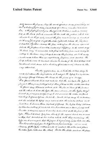
will assume the purpose. But the most effective mode of providing in this is to let a perpendicular pin extend up or down from the common bar (the proper point to give the required motion) make a square hole in the link which connects the bar with the rollers which hole should be so large as to prevent the pin from coming in contact with any part of it except the side against which the pressure is exerted. By this means the pin rolls upon the surface against which the pressure is exerted, instead of slipping in the usual way. The link may be connected with pins extending from each end of the roller in the same way as to avoid the friction at each end. In small cases where there is considerable pressure and motion the part which comes in contact should be made of the best steel and hardened and, more upon sections of circles and planes in the way described.
Another application in which the rollers may be used, is to press the impression with adapt the types to a cylinder by using spaces between the lines in the form of a ridge. These spaces should be cast as far into the nicks in the type to prevent them from falling out of their places as the roller revolves. The spaces may likewise extend into the form in the form so that the chase to hold the type the more secure, or the type may be cast in forming a wedge so as to set around the roller without reaching to spaces between the circles. Small rivets may be introduced into the nicks of the types once extend into the circular chase and fasten to secure them instead of spaces. The types being set upon similar rollers, if suitable, to contain one or more forms, each two other rollers are used to revolve in contact with the face of the type. Blankets and type space sheets of the usual kind are used on these last mentioned two rollers which, with those containing the type, are so arranged that the paper to be printed passes between them. Thus let a sheet of paper be straightened horizontally at one end, place one of the type rollers under it and at the other end place the other type roller over the sheet. Under the latter and over the former
Page 5.
United States Patent
Patent No.: X3668
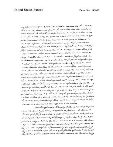
are placed the separate rollers on which are wound, the blankets etc. These are all to be connected together by cog wheels that they move in exact concert: so that the register is made more perfect than it can be in the usual way. One of the cog wheels is connected with its type roller by a cross so that its position can be changed at pleasure in making registers. It is intended that may be passed between these rollers, and so inked with great sharpness on both sides by first touching it upon a roller, while wetting it once there passing it between those above described, and after leaving these it may be either wound upon another roller or passed off to dry in the same manner, as it is dried in the paper staining business. Each of the type rollers is supplied with ink by three or more rollers having their rollers closely wound round them and covered with the same leather or skins with which the common printers' plates are covered; these rollers in contact with the face of the letter area are supplied by another roller which passes to and fro round the outside of the whole touching each as it moves. This may be supplied by other distributing rollers (revolving) on their axes by the motion of either of either of those first mentioned) to which the ink is applied by a common tray or by a cylinder brush revolving in a vessel containing ink. The ink may be equalized on the distributing rollers by a small roller moved by machinery or by hand backwards and forwards across them or it may be equalized in this manner on a board, and then applied to the rollers.
The other apparatus belonging to the subscribers' improvement in the art of printing is described as follows: The bed and platter of the press are to be each of the side of the forms to be printed. The bed is placed horizontally obliquely or perpendicularity and the platter is brought to it in the same manner and to answer the same purpose as the common type press; and when it is brought down on the form the impression is produced by an application of the press, sure before described upon the end of the platter opposite to the hinge. The platter is then raised and the sheet removed in the usual way.
Page 6.
United States Patent
Patent No.: X3668
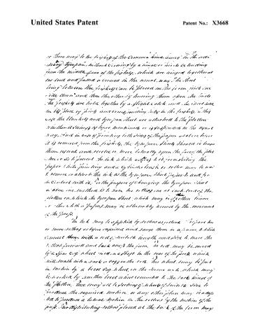
There may be the friskies of the common kind, being in the order of many types, without covering by a hinge or such extending from the middle of one of the friskies, which are hinged together at one end and passed or covered in the usual way. The sheet being between the friskies can be placed on the form just one side down and then the other by turning them upon the friskies. The friskies are held together by a slight catch and the sheet is held in its place by pins and corresponding holes in the friskies. In this case the blankets and tympan sheet are attached to the platen whether it is hinged or before mentioned or is suspended in the usual way. But in case of printing both sides of the paper as above before it is removed from the friskies, the tympan sheet should be kept more or less vertical and receive or move laterally upon the face of the platen so as to prevent the ink which adheres to it from smearing the paper while printing and a cylinder brush or roller may be used to remove or absorb the ink as the tympan sheet passes to and fro in contact with it. For the purpose of changing the tympan sheet in the one method is to have two rollers, one at each end of the platen on which the tympan sheet which may be of cotton, linen or other cloth or paper, may be alternately removed by the movement of the friskies.
The ink may be applied by rollers as follows. Prepare two or more rollers as before described and range them in a frame, to which connect them with a rod of suitable length and size to move the rollers forward and back across the form. The rod may be moved by a gear wheel fixed in a shaft in the rear of the press, which will mesh into a rack or cog on the rod. The wheel may be put in motion by a bevel gear wheel, in the same as a wheel which may be worked by another bevel wheel connected to the back hinge of the platen. There may be a reflecting wheel of suitable size to produce the required motion, or any other plan may be adopted to produce a lateral motion in the rollers by the motion of the press. The distributing rollers placed at the back of the form may
Page 7.
United States Patent
Patent No.: X3668
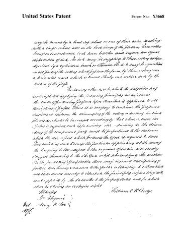
may be turned by a level cog wheel on one of their axes, meshing with a larger wheel also on the back hinge of the block. These rollers being in contact will both turn together and insure an equal distribution of ink. The ink may be supplied to these rollers as before described by a cylindrical brush or otherwise. The ink may be equalized on all parts of the rollers which pass over the form by their rolling over a horizontal board which is turned slowly on a vertical axis by the motion of the press.
The various other uses to which the Subscriber has contemplated applying the foregoing principles are as follows: The mode of producing pressure before described is applicable to all descriptions of presses. Where it is necessary to continue the pressure a considerable distance the dimensioning of the rollers or rocking motion planes, etc., should be increased accordingly. But where a mere increase is required such as in turning, etc., depending on the dimensioning of the component parts must be proportioned to the distance which the die or part which produces the effect is required to move. These variations and likewise the particular applications which among the foregoing is best adapted to the required operation will readily suggest themselves to the skilled artist who contemplates the machine in the preceding specification. There may be some descriptions of parts of machinery common to the public or belonging to others which are introduced merely to illustrate the principles originating with and explained by the Subscriber to the purposes stated and for which alone he claims an exclusive right.
Witness
William C. McGeorge
End. Henry H. Lee & M.G.
Page 8.
United States Patent
Patent No.: X3668
DRAFTSMAN'S DIVISION.
All communications should be addressed to
“The Commissioner of Patents,”
Washington, D. C.
DEPARTMENT OF THE INTERIOR,
United States Patent Office,
Washington, D. C., 189
SIR:
The printed copies of Patent No. 2,328 a.
are exhausted.
As soon as printed a copy will be mailed you to complete your order.
By direction of the Commissioner:
Very respectfully,
Chief Clerk.
814316-57-5m
About this record
- Patentee
- DATAMP
- Date
- the Name and Date index of patents, DATAMP, USPTO records
- Invention
- DATAMP
- Listed in
- the Name and Date index of patents, DATAMP, USPTO records, Jim Shaw's X-patent list, Burke's List of Patents (1847)
- Burke's 1847 Patent Office list gives the same patent.