

Drawings and documents
National Archives restored drawings: drawing
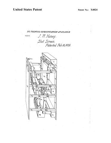
J. W. Honey's Patent Drawing for a Screening Table for Discriminating, Detecting, and Separating Perfect from Imperfect Shot

National Archives, Restored Patent Drawings (Record Group 241) · Full-size scan at the National Archives · Catalog record
Show the text on the drawing Hide (149 words)
Words on the drawing as machine-read by the National Archives; not checked. Useful mainly for searching.
J.W.HONEY'S / 60 / Screening-Table for discriminating ,detectingiseperalinsperfectfrom iniperfect that. / Patented Foby. 10th 182.5. / STASSIFICATION / 4024 / I's / 10 / OR / 11 / IR N Thy E IR TE IV C TE S. / on / A. The frame which supports the machinery'. B, the hopper C. the metalie regulating pans D.the serewing iables / with their sides A2° casings E, the sliding inclined planes, with their sides or frome work. E condu- / cling cases of imperfeci shoi, G. recierer wirh an inclined boliom H, reciever for imperteei shol I reversed ineti / nea plane for imperfeci shois ils casing" K reversed inclined plane for imperfecis perfect thoi / mingled iogother mith their casings is frame - work. L box for perfeci shoi M,head or eleraied end of / one iable shewing ihe reveised order. N, chord aliached io the regulating pans
USPTO scan
The patent as scanned by the USPTO
-
 Page 1
-
 Page 2
-
 Page 3
-
 Page 4
-
 Page 5


U.S. Patent and Trademark Office · Google Patents
Show the transcription Hide (1,440 words)
Machine transcription (LightOnOCR) of the pages as scanned by the USPTO, most of them the handwritten copies made when the records were restored after the 1836 fire. Not checked; it can misread handwriting, so compare it with the scan.
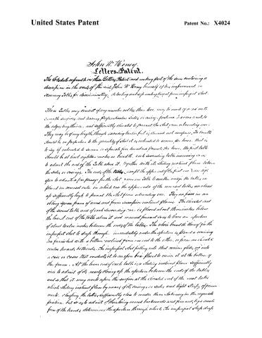
Page 2.
United States Patent
Patent No.: X4024
John W. Hancey.
Letters Patent.
The Schedule or formula in these Letters Patent, and making part of the same containing a description in the words of the said John W. Hancey himself of his improvement in screening tables for discriminating, detecting and separating imperfect from imperfect shot.
These tables may consist of any number not less than two, may be made of iron or well smooth surfaces and having perpendicular sides or casing, fastened to a cross beam, to the edges lengthwise, and sufficiently elevated to prevent the shot from rebounding over. They may be of any length, though exceeding twelve feet is deemed not necessary. The breadth should be in proportion to the quantity of shot it is intended to screen per hour. That is to say if intended to screen or separate five hundred pounds per hour, the first table should be at least eighteen inches in breadth. Each succeeding table increasing so as to admit the end of the table above it, together with its sliding inclined plane between the sides or casings. The ends of the tables except the upper end of the first one are kept open to admit a free passage for the shot from one table to another until the tables are placed in reserved order in which case the upper ends of the reserved tables are raised up sufficiently high to prevent the shot from rebounding over. They are fixed in an oblong square frame of wood and form successive inclined planes. The elevated end of the second table and of each succeeding one is placed about three inches below the lowest end of the table above it and removed forward so as to leave an aperture of about twelve inches between the ends of the tables. The whole breadth thereof for the imperfect shot to drop through, immediately under the aperture is placed a screening box furnished with a bottom inclined from one end to the other, or from one elevated centre towards both ends. The imperfect shot falling into that screen glides off into a case or cases that conducts it to an open box placed to receive it at the bottom of the frame. At the lower end of each table is a sliding inclined plane sufficiently wide to admit of its nearly closing up the aperture between the ends of the tables and so that it may work upon the surface at the elevated end of the next table which sliding inclined plane by means of its casings or sides and light strips of prime work, closing the tables sufficiently close to render them stationary in the requisite position, but so as to admit of their being moved backwards and forwards by a small force of the hands, determines the aperture through which the imperfect shot drops.
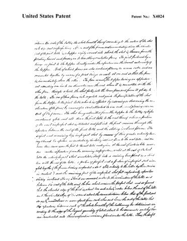
Page 3.
United States Patent
Patent No.: X4024
between the ends of the table, the whole breadth thereof according to the nature of the shot as to size and imperfections. At one end of the frame and immediately above the circular end of the first table is a hopper simply secured into which the shot is thrown from the preceding barrel and passes on to two elongated table pans. The first fastened by a hinge or joint to the hopper directly under the aperture in the lowest extremity of the hopper. Both of which pans are also inclined planes in reverse order and are connected together by means of a joint hinge or swivel at one end so that the pan is immediately above the other. The pan nearest the hopper having an aperture not extending one inch in diameter near the end when it is connected with the other pan. Through which the shot falls into the lower pan and from it glides to the table. The use of these pans is to regulate and guide the precipitation of the shot from the hopper to the first table which is effected by increasing or decreasing the inclination of the pans by means of a cord attached to one end, and passing over one end of the frame. The shot being admitted from the hopper to the tables as before mentioned glides and rolls down the first table to the end thereof where a portion of the most imperfect shot is detected and falls into the first receiver through the aperture between the end of the first table and the sliding inclined plane. The perfect and remaining less imperfect shot by reasons of their greater velocity having cleared the aperture are conducted by the sliding inclined plane to the next table, and continue their course from the first to the last table underpins at the end of each in the manner without separation from the remaining imperfections, until at the end of the last table the entirely perfect shot precipitates itself into a receiving box placed in a sliding line with the end of the table. A portion of perfect and a portion of imperfect shot mingled together (the former having imparted a part of its velocity to the latter by their coming in contact) and the remaining part of the imperfect shot fall respectively upon two sliding inclined planes placed in reverse order to the inclination of the table and between the end of the table and the box which receives the perfect shot, and so framed that the elevated edge of the first is about two and a half inches below the end of the table, and the elevated edge of the second about the same distance below that of the first, and so as to move closer or more apart from each other and from the end of the table that the apertures between each of the whole breadth of the table may be determined according to the size of the largest quantity of shot about to be screened, and by them are conducted into their respective receivers placed under the table. Thus the perfect
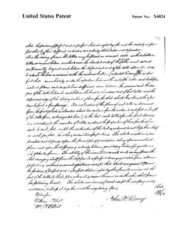
Page 4.
United States Patent
Patent No.: X4024
shot, the portions of perfect and imperfect shot mingled together and the entirely imperfect shot by their different velocities are entirely distributed and separated.
For the saving of room the tables may be placed in reversed order, with a table on tables above and below, in which case the elevated ends of the tables must extend sufficiently beyond and below the depressed end of the table above it, so as to admit the box or receiver with the inclined bottom (intended to carry the imperfect shot) immediately under the aperture between the end of the table and its sliding inclined plane, and so as to leave sufficient room between the receiver and the upper space of the table below it, and between the head or elevated end of that table and the depressed edge of the sliding inclined plane for the shot which has cleared the aperture to find a free passage; The inclination of the plane of each table is decreased from the first (which is elevated about two and one from the inches to each foot in length of the table from a horizontal line) to the last, each table after the first decreasing, according to the number of tables, in about the proportion of three-fourths of an inch to each foot, until the inclination of the last is reduced to not less than half an inch per foot, the others in arithmetical proportions. The whole machine is constructed and depends upon the principle of gravitation acting upon an inclined plane, and upon the difference of velocity between gravitating bodies of a greater or less globular form. The utility of the invention consists in its saving power the shot, carrying itself from the hopper to a perfect disengaged state from all imperfections, without manual assistance except that which is required to move the portions of perfect and imperfect shot mingled together, from its receiver at the foot of the tables, to the hopper where it is again thrown in with the other shot from the positioning barrel. The whole machine is of wood except the necessary irons and screws to keep it together and the regulating gears.
Witnesses
William Elliot
Wm. O. Elliot
John M. Gorney
(642)
M.G.
Page 5.
United States Patent
Patent No.: X4024
NO PRINTED SPECIFICATION AVAILABLE
4024X
J. M. Honey.
Shot Screen.
Patented Feb. 10, 1885.

About this record
- Patentee
- Jim Shaw's X-patent list
- Date
- the Name and Date index of patents, USPTO records, Jim Shaw's X-patent list
- Invention
- the Name and Date index of patents
- Listed in
- the Name and Date index of patents, USPTO records, Jim Shaw's X-patent list, S. A. Elliot's printed list of patents, Burke's List of Patents (1847)
- S. A. Elliot's printed list of patents gives the same name and date.
- Burke's 1847 Patent Office list gives the same patent.