

Drawings and documents
USPTO scan
The patent as scanned by the USPTO
-
 Page 1
-
 Page 2
-
 Page 3
-
 Page 4
-
 Page 5


U.S. Patent and Trademark Office · Google Patents
Show the transcription Hide (1,296 words)
Machine transcription (LightOnOCR) of the pages as scanned by the USPTO, most of them the handwritten copies made when the records were restored after the 1836 fire. Not checked; it can misread handwriting, so compare it with the scan.
Page 2.
United States Patent
Patent No.: X4055
A. L. Peller
Letters Patent
The Statute referred to in these Letters Patent and, making part of the same containing a description in the words of the said A. L. Peller himself, of his improvement in changing the motion of machinery.
It is known that the said A. L. Peller has invented and constructed and applied to use a new and useful improvement for producing any required change in the velocity of machinery while in motion. The following is a description of the said invention and of the manner of using the same.
I take two cylinders of iron or other metal, placing the same parallel to each other at a convenient distance apart. One of the cylinders has a uniform rotary motion communicated to it by means of a wheel driven at either end. The other is fixed upon this cylinder a series of cog wheels contiguous to one another of various sizes. There is also placed upon the other cylinder a series of cog wheels contiguous to one another and having such a proportion to the former series as that being constantly in contact with the former, there is communicated to each of the latter a certain required velocity. The latter wheels are not fixed but revolve separately on the cylinders as in an axis. The object now is to produce this required at different times, the various degrees of velocity with which the wheels are placed upon it move. This object is effected by placing firmly upon the cylinders one of the wheels at a time, and then bringing it and immediately fixing the wheel contiguous to the different wheels thus communicating successively to the cylinders their proper velocities. These wheels are more precisely placed and arranged in the following manner: in cylinders on which they are mounted there is a hole in which is mounted into it a small cone frame much like the motion frame of an hour glass which is made to each casing within the cylinder, on one side of this frame is placed a spring which is mounted in it moving along a slot or groove made through the side of the cylinder. The wheel rotating a little without the cylinder. The inner surface of each of the movable wheels is notched so that when the wheel is moved the wheel goes into
Page 3.
United States Patent
Patent No.: X4055
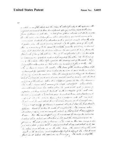
a notch on one of the wheels and then, when the wheel finally to the cylinder. It is found convenient to have two separate springs catches fixed to the iron frame mechanism in each side. In that if one of them should not strike a notch the other will. The slider frame above described is moved by means of a screw rack to which it is attached with a screw. So as to allow the slide to move when the rack moves at rest. In the upper side of the rack there is a number of teeth equal to half the number of teeth on the end wheel and limited the distance between the several teeth being twice the thickness of one of the wheels. These teeth are formed after by two steps or hammer, one of which is placed forward of the other. The thickness of one of the wheels. These steps regulate the turning out of the rack. The first letter alternates so that when one is moving to free a tooth, the other is down to secure the next. The time of the motion of these steps is accurately regulated. So as to allow the cylinder to move within no strain of action, as may be required. When the cylinder is to be charged the hammer which lifts the rack wheel rises and the rack is thrown out the back of the cylinder, when it is stopped again by the other hammer the rack is thrown out by means of a snap and weight. When all the movable wheels have been released when the rack is at rest or means of a pinion working against the teeth on the underside of the rack, such as not in a minute. The wheels pass a wheel from which they are not in it. The other wheels have, when a screw or roller at one end the pin and the wheel which the rack passes, running in its circumference.
In a great variety of changes is required it is best that the first described cylinder should be built to render it as possible. The manner above described of driving and reversing the wheels is that which I have applied to use. But the same effect may be produced by having the cylinder in which these wheels are attached, while and the other moving in a groove on the side of the cylinder. The side in this case being a rim, is not a plate of iron with a spring catch at one end which is to free the wheel when the wheel is in the other case. The groove being the wheel length on the cylinder and sufficiently deep to admit the slide to move freely in it while the cylinder is turning. The outer end of the
Page 4.
United States Patent
Patent No.: X4055
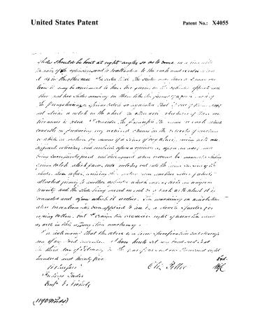
slides should be bent at right angles so as to come in a line with the axis of the cylinder, and it is attached to the rack and pinion as it is in the other case. It is also that the slides may have a greater motion; it may be convenient to have the grooves in the cylinder opposite each other and two slides moving in them like the forms of paper in which the fingers having a spring action so arranged that if one of them is not struck a notch in the wheel in other words, the motion of these two mirrors is such. I consider the principle the same in each which consists in producing any motion or change in the tracks of motion which is motion by means of a series of any wheels, moving with different velocities and moving upon a cylinder, as upon an axis, and being successively placed and disposed upon them, means for means, sliding upon each, which passes into notches cut into the inner surfaces of the disks, these notches receiving the motion from another series of wheels attached primly to another cylinder which moves with an uniform velocity, and the slides being moved on and to a track with which it is connected and upon which it moves. The machinery in which this invention has been applied to use is a device of Parker for roving cotton. But I claim the exclusive right of using the same as well in this roving machine.
I certify that the above is a true specification and description of my said invention. I have hereunto set my hand and seal this 13th day of February, in the year of our Lord one thousand eight hundred and twenty-five.
Witnesses:
W. H. H. H.
W. H. H. H.
W. H. H. H.
(119091010)
Page 5.
United States Patent
Patent No.: X4055
DRAFTSMAN'S DIVISION.
All communications should be addressed to
"The Commissioner of Patents."
Washington, D. C.
2-328 a.
DEPARTMENT OF THE INTERIOR,
United States Patent Office,
Washington, D. C., 189...
SIR:
The printed C. J. Fries
and exhausted.
As soon as printed a copy will be mailed you to complete your order.
By direction of the Commissioner:
Very respectfully,
Chief Clerk.
314316-97-5m
About this record
- Patentee
- Jim Shaw's X-patent list
- Date
- the Name and Date index of patents, USPTO records, Jim Shaw's X-patent list
- Invention
- the Name and Date index of patents
- Listed in
- the Name and Date index of patents, USPTO records, Jim Shaw's X-patent list, S. A. Elliot's printed list of patents, Burke's List of Patents (1847)
- S. A. Elliot's printed list of patents gives the same name and date.
- Burke's 1847 Patent Office list gives the same patent.