

Drawings and documents
USPTO scan
The patent as scanned by the USPTO
-
 Page 1
-
 Page 2
-
 Page 3
-
 Page 4
-
 Page 5
-
 Page 6
-
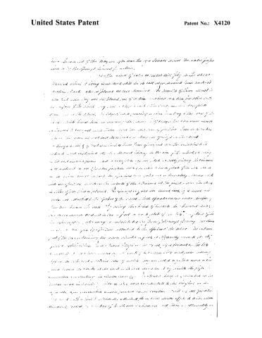 Page 7
-
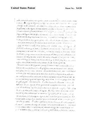 Page 8
-
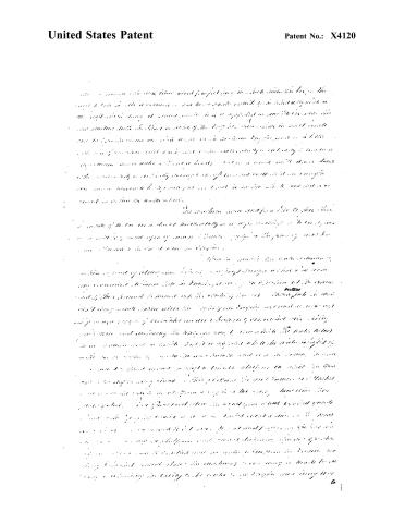 Page 9
-
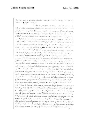 Page 10
-
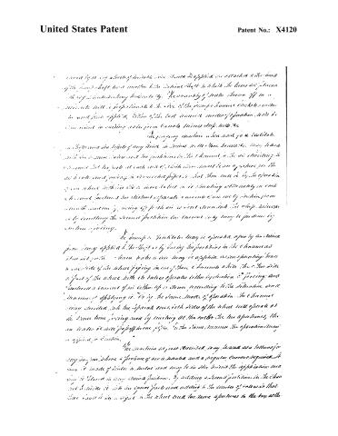 Page 11
-
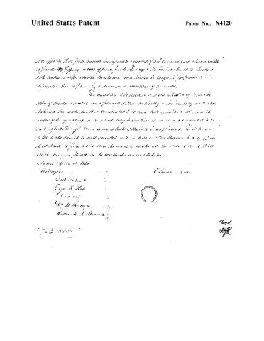 Page 12
-
 Page 13


U.S. Patent and Trademark Office · Google Patents
Show the transcription Hide (3,380 words)
Machine transcription (LightOnOCR) of the pages as scanned by the USPTO, most of them the handwritten copies made when the records were restored after the 1836 fire. Not checked; it can misread handwriting, so compare it with the scan.
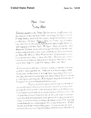
Page 2.
United States Patent
Patent No.: X4120
Elsie D. Hale
Letters Patent
The Schedule referred to in these Letters Patent and contained in the specification is the following:
In the preceding description, it is stated that the invention relates to a new and improved method of operating a steam engine. The invention consists in the use of a new type of valve gear which operates on the principle of a rotary principle which is applied to the steam engine. The engine having a certain number of cylinders, the valve gear is arranged to operate in such a way that the steam is admitted to the cylinders in a manner which is more efficient than the conventional method.
The above-mentioned machine is constructed of a machine consisting of a series of parts which are arranged in a specific order. The parts are connected together by means of a series of rods and levers which are arranged to operate in a coordinated manner. The machine is designed to be operated by a single person who can control the entire operation of the machine by means of a single lever.
The invention is particularly useful in the operation of large steam engines which are used in industrial applications. The new valve gear allows for a more efficient use of steam and reduces the amount of fuel required to operate the engine. The machine is also designed to be easy to maintain and repair, which makes it a practical choice for industrial use.
In conclusion, the invention described in these Letters Patent is a significant improvement in the operation of steam engines. The new valve gear allows for a more efficient use of steam and reduces the amount of fuel required to operate the engine. The machine is also designed to be easy to maintain and repair, which makes it a practical choice for industrial use.
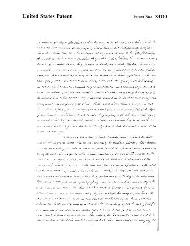
Page 3.
United States Patent
Patent No.: X4120
In minute of action in the sheet so that he may be in operation at a time, as is the case with the machine on the property, then though not indispensable, necessary to make the same be, may be discharged at any point, so as to be performing its functions, while when in the sheet its operation is that, while the chamber around the axis of one entire circle, may be used in each part, plate of the box. A chamber in a split and with a vent equal to one twenty inches, and in each edge of the box, there are units, may be varied according to particular application of the machine per, per, etc., a different or better value, which is not quite, but to be used in a manner which should be much larger and the box, and chamber proportionate to same. The valve of the chamber must be made standing on a sharp to be used in the cutting of the tubes so that they may turn around in it, the entire time being made to conform to the periphery of the wheel. If the valve of the chamber is a general half, there is in each plate of the box, a depth and width about equal to one fifth of the depth of the chamber, and if the valve is to receive the periphery of the wheel, and in each edge of a certain width of the chamber must be made so as to allow it to meet with the periphery and a number of points, made in the edge of each plate to receive a wire or rod to prevent damage.
*In this way, a wheel of such diameter and inches as will be with the given unit, there are the edges of the partition inside of the chamber, and in each side of the rim, a diameter, quite round to be uniform, each side in depth and diameter of the same, which measures not close to the inside of the wheel, and a depth of which partition is about as thick as the thickness of the rim, while the rim is the same, while the rim are three or more of inches, so the tubes are only one and a half inch, to be chamber under the same dimensions, and that is with just equal to the setting the opposite angle, the thickness of the rim and through the center of the rim, a point passing from the rim to a point exactly in the center, and a diameter, so that the tubes must be tubes are going, and by such a tube, there is more the same, except the point so that the array of the same, and the at right angles to the rim, the rim each in length about equal to its diameter, where the tubes, in the same manner, a wire, there are equal to that of the other, so as to be, where, while are same, when to give them, so the wires in the center, so that the turn of the same. The ends of the tubes are being, and the rim, the same, and the same, to make it conform to the circle, and that of the same, the
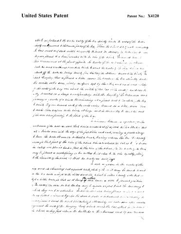
Page 4.
United States Patent
Patent No.: X4120
which are fastened to the circle cavity of the box directly under the arms of the base, and secured to the main plate of the box, when the base is at a point midway the base must be of such width as to easily to insert the arms, the latter being so arranged that they are placed in a line parallel with the rim of the wheel. The arms are so arranged that they commence at the point opposite the center of the wheel, and extend to the circumference of the circle to about the center of the box, with a small stub off the base, being nearly five digits of the distance from the center of the wheel hanging. Bar is placed a little nearer the center of the box directly under the inside of the arm, giving the space left by the box, and so it is arranged that the ends of the long arm about the width of the bar with ends; each has a long segment in a shape corresponding with the length of the base arm and forming a portion of a circle terminating at a point just below the box. The box is divided; they are secured each of the ends being moved in a little more than to make them conform to the circle at large, and so as easily to meet the end of the arm when pointing to the plate of the box.
In reference between an aperture, or the substance of the main box, and that which connects it off a little with a block, that at a little near with the edge of the partition each end, forming a gentle slope to turn the base, then without a break, having between the two blocks only room for that part of the rim of the wheel which contains the holes to be driven the bases are placed under flat to the rim of the wheel, in the center of the box may be placed a weak spring or two setting to sit close to the rim equally, fitting to the circumference of the wheel, so that no tension is felt.
In use as, more in the center of the box, and it should not be against each plate of it, or it may be made to rest on the box with rings in the sides and the wheel to either closely attached or kept a little loose, so that as it turns the wheel a little to prevent friction.
The ends of the arms, when the box may be square or flat, point the mounting to which they are to be attached. In this case, the arms being placed in the box, and the box fitted a second by the same means to make a continuous motion, so that the movement turns the wheel which brings ultimately one into an open position, and against the rest of the hanging bars which move the box, that is the wheel as they pass between the two blocks in the chamber and by one arm
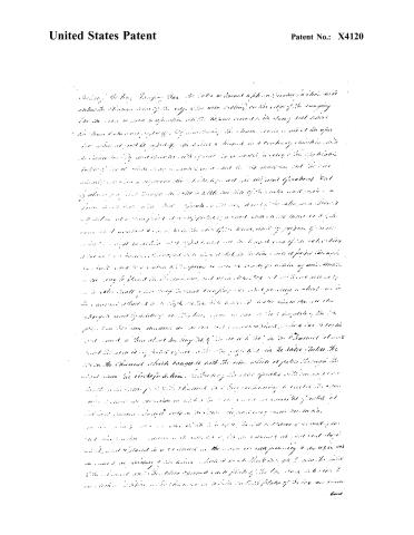
Page 5.
United States Patent
Patent No.: X4120
*During the long flowing that the water is turned up and down, the water is under the influence of the edge of the water moving on the edge of the moving face the water is seen to spin when the water comes to the edge and moves the same before being stopped by the water being in a way of the …
Page 6.
United States Patent
Patent No.: X4120
Handwritten text, largely illegible due to poor quality and distortion.
Page 7.
United States Patent
Patent No.: X4120
This document contains handwritten text that is largely illegible due to poor image quality and faded ink. The following is an attempt to transcribe the visible portions, but many words and phrases remain unreadable or ambiguous.
The text appears to describe a mechanical or engineering device, possibly related to a pump or valve system, with references to components such as “springs,” “plates,” “cylinders,” and “valves.” The handwriting is cursive and often overlapping, making precise transcription challenging.
Key phrases that can be partially deciphered include:
- “...the manner of the way in which a small wheel...”
- “...the spring... inside...”
- “...the plate... is placed...”
- “...the cylinder... is moving...”
- “...the valve... is opened...”
- “...the piston... is pushed...”
- “...the fluid... is forced...”
The document appears to be a patent specification, detailing the operation and construction of a mechanical device. The text is structured in paragraphs, with some sentences beginning with capital letters and others continuing from the previous line.
Due to the poor quality of the image and the cursive handwriting, a complete and accurate transcription is not possible. The following is a best-effort transcription of the visible text:
The device includes a spring mechanism that is compressed when a plate is moved into position. The spring is attached to a rod that is connected to a cylinder. When the cylinder is moved, it pushes against the plate, causing the spring to compress. The spring then expands, pushing the plate back into its original position. This process is repeated as the cylinder moves back and forth.
The text also mentions a valve that is controlled by the movement of the plate. When the plate is in one position, the valve is open, allowing fluid to flow through the system. When the plate is in another position, the valve is closed, preventing fluid from flowing.
The document concludes with a description of the overall operation of the device, emphasizing the importance of the spring mechanism in maintaining the proper position of the plate and valve.
Page 8.
United States Patent
Patent No.: X4120
The text below is handwritten and largely illegible due to poor quality and distortion. The following is an attempt to transcribe the visible portions, but much of the content remains unreadable.
...with the side of the wheel, so the engine is just as much a part of the wheel as the wheel is part of the engine. The way the engine is mounted, it seems that the wheel is so heavy on the side it is the side of the engine that is the main support. The position in the engine is connected by a pipe in the form of a tube or a hose through a series of tubes or ducts. The engine is mounted on a frame that is attached to the floor of the room, so it is not a movable unit. The pump is mounted on the floor, and the water is drawn from the well and pumped up through the pipe to the engine. The water is then pumped into the tank or reservoir. The engine is connected to the pump by a belt or chain, and the water is pumped up through the pipe to the tank. The tank is located above the engine, and the water is stored in the tank until it is needed. The water is then pumped down through the pipe to the well, and the cycle is repeated. The engine is powered by steam, and the steam is generated by burning coal or wood in a boiler. The steam is then directed to the engine, where it is used to drive the pump. The engine is then turned off, and the steam is allowed to cool. The cycle is then repeated. The engine is a simple machine, and it is easy to understand how it works. The engine is also very efficient, and it is able to pump a large amount of water with very little effort. The engine is a great tool for farmers and ranchers, and it is used to pump water for irrigation and livestock. The engine is also used to pump water for drinking and cooking. The engine is a very useful tool, and it is an important part of many farms and ranches.
Page 9.
United States Patent
Patent No.: X4120
This document contains handwritten text that is largely illegible and cannot be accurately transcribed into Markdown format. The visible text includes the patent title and number, but the body of the document is obscured by handwriting that does not form coherent or readable content.
Page 10.
United States Patent
Patent No.: X4120
In a review from around the last evening, I had at the top, placing the sheet and plugging into it.
*This is the machine as I have described it, and I have not yet realized a satisfactory result in a machine. This pump, performing its function simply by means of a valve and connecting it to a close pipe using one of the valves in the box at the bottom that is connected to the pump, the valve is not of the same as a piston or piston and not of brass. The valve is not a valve, but a piston which is placed through the pump and is not a piston, but a piston. The …
Page 11.
United States Patent
Patent No.: X4120
...and by it any sheet of suitable size when applied in a manner to the head of the pump shaft, and another to the vertical shaft to which the beams are joined with any suitable working kinematics. The quantity of water thrown off in a minute will be proportional to the size of the pump chamber or chambers, and the amount of air applied. Either of the last named modes of operation will be sufficient in raising water from Canal, Mine, etc.
The pumping machine when used for a limited... a higher and a depth of any kind in mines, wells, etc., may be used with the same ease and the position in the channel, or in elevating... the water... at such a rate... that there will be by the operation... from which the water is more... in it circulating alternately in each channel... and the distinct separate currents... by suction... and by pushing the second partition... current... by suction... pushing.
The pumps or ventilators may be operated separately or simultaneously... by having the partitions in the channel... the water... may be applied... on one side of the wheel... while the other side... is part of the wheel... with its water operates... by suction... and... a current of air... up or down... according to the direction... of applying it. By the same mode of operation... the channel... being divided into the separate ones, both sides of the wheel will operate at the same time, being moved by moving at the ends... the two apertures... the water... to the pipe... in the same manner the operation may be applied... in suction.
*The machine as just described may be used as a bellows for any purpose where a pressure of air is desired and a regular current required. It may be made of plates or tubes and may be in size to suit the application and may be placed in any desired position. By adding a second partition in the channel... and dividing it into two equal parts and attaching to the sides of water... that there will be a jet... in the wheel... two more apertures in the box at the...
Page 12.
United States Patent
Patent No.: X4120
This apparatus is designed to operate in a manner similar to that of the first described apparatus, but with the addition of a new feature which allows for greater flexibility in operation. The apparatus is intended to be used in conjunction with the previously described apparatus, and is designed to be easily integrated into existing systems.
The apparatus is constructed from a variety of materials, including metal, plastic, and rubber, and is designed to be durable and long-lasting. The apparatus is also designed to be easy to use, with simple controls and intuitive interfaces.
The apparatus is intended to be used in a variety of settings, including homes, offices, and industrial facilities. The apparatus is designed to be versatile and adaptable, allowing for a wide range of applications.
The apparatus is designed to be energy efficient, with low power consumption and minimal environmental impact. The apparatus is also designed to be safe to use, with built-in safety features to prevent accidents.
The apparatus is designed to be easy to maintain, with simple cleaning procedures and minimal maintenance requirements. The apparatus is also designed to be easy to repair, with readily available replacement parts and instructions.
The apparatus is designed to be user-friendly, with clear instructions and helpful guidance. The apparatus is also designed to be accessible to a wide range of users, including those with disabilities.
The apparatus is designed to be cost-effective, with competitive pricing and value for money. The apparatus is also designed to be a good investment, with a long lifespan and minimal downtime.
The apparatus is designed to be innovative, with cutting-edge technology and advanced features. The apparatus is also designed to be reliable, with consistent performance and minimal errors.
The apparatus is designed to be sustainable, with eco-friendly materials and processes. The apparatus is also designed to be responsible, with a commitment to environmental stewardship and social responsibility.
The apparatus is designed to be future-proof, with the ability to be upgraded and expanded as technology advances. The apparatus is also designed to be scalable, with the ability to be used in a variety of sizes and configurations.
The apparatus is designed to be secure, with advanced encryption and authentication features. The apparatus is also designed to be compliant with industry standards and regulations.
The apparatus is designed to be user-centric, with a focus on meeting the needs and preferences of the end user. The apparatus is also designed to be intuitive, with easy-to-use controls and clear feedback.
The apparatus is designed to be innovative, with a focus on pushing the boundaries of what is possible. The apparatus is also designed to be visionary, with a commitment to exploring new and exciting possibilities.
The apparatus is designed to be reliable, with a focus on consistent performance and minimal downtime. The apparatus is also designed to be durable, with a commitment to long-term use and minimal maintenance.
The apparatus is designed to be sustainable, with a focus on environmental stewardship and social responsibility. The apparatus is also designed to be responsible, with a commitment to ethical and ethical practices.
The apparatus is designed to be future-proof, with a focus on adaptability and scalability. The apparatus is also designed to be secure, with a focus on privacy and security.
Page 13.
United States Patent
Patent No.: X4120
DRAFTSMAN'S DIVISION.
All communications should be addressed to
"The Commissioner of Patents."
Washington, D. C.
DEPARTMENT OF THE INTERIOR,
United States Patent Office,
Washington, D. C., 189
SIR:
The printed copies are exhausted.
As soon as printed a copy will be mailed you to complete your order.
By direction of the Commissioner:
Very respectfully,
Chief Clerk.
814314-07-5m
About this record
- Patentee
- Jim Shaw's X-patent list
- Date
- the Name and Date index of patents, USPTO records, Jim Shaw's X-patent list
- Invention
- the Name and Date index of patents
- Listed in
- the Name and Date index of patents, USPTO records, Jim Shaw's X-patent list, S. A. Elliot's printed list of patents, Burke's List of Patents (1847)
- S. A. Elliot's printed list of patents gives the same name and date.
- Burke's 1847 Patent Office list gives the same patent.
- Residence from Burke's 1847 Patent Office list; the standard lists give none.