

Drawings and documents
USPTO scan
The patent as scanned by the USPTO
-
 Page 1
-
 Page 2
-
 Page 3
-
 Page 4
-
 Page 5


U.S. Patent and Trademark Office · Google Patents
Show the transcription Hide (2,314 words)
Machine transcription (LightOnOCR) of the pages as scanned by the USPTO, most of them the handwritten copies made when the records were restored after the 1836 fire. Not checked; it can misread handwriting, so compare it with the scan.
Page 2.
United States Patent
Patent No.: X4125
Henry Wardell,
Letter Patent. Patented May 26, 1825
The Schedule referred to in these Letters Patents, and making part of the same, containing a description in the words of Henry Wardell himself, of his improvement in the manufacture of wrought nails or spikes, solely by the aid of machinery.
I make use of a fixed frame of cast or wrought iron, the side pieces and ends being four inches square, longer or shorter as may be deemed necessary. The one now in operation is four feet long and eighteen inches wide; inside, at the one end of the frame is fixed the crank shaft, on which is thimble, wheel and pulley, from which belt or other gearing may be attached to give motion to the machine. About the middle of the fixed frame, two rods, a part of which is under the other projection above the frame through which the rollers move on their centers or axis which rolls out the nail. On the inside of the fixed frame are four brasses on which the moving frame slides forward and back. These brasses, two of which are movable (inside lying in grooves in the fixed frame) by means of screws bolts passing through the sides of the fixed frame; to make the moving frame play tight as occasion may require. The moving frame may be made of cast or wrought iron, the one now in operation is cast iron, two feet long and eighteen inches wide, resting on the brasses at the four corners. On the end of said frame is attached the pitman or connecting rod which, being connected with the crank, gives motion to the machine. The side of said frame is fastened a straight rack seven inches long, having cogs in it to give motion to two rollers which swedge or roll out the nail. In the same side of the moving frame to which is fastened is a place for one of the side steel between which the rod is fastened. This steel is about one inch thick, three inches wide and the length of the nail required, is moved as occasion may require, by screw bolts on the side and ends. Opposite this steel a bout two inches distant is a moving lever, one end of which is fastened through a mortise by means of a bolt or pin in the one end of the moving frame. In this lever is a place for the other side steel, the dimensions of which is the same as the one above described, and is fastened by bolts in a similar manner. By means of these bolts, the side steels may be moved so as to admit the rod and swedges or rollers that roll out the nail. Parallel with the side steels and on a line with the center of the lever is the header, three of which being set at the distance of the thickness of the head from the ends of the side steels. This header moves in a mortise or groove by a crooked line of cast or wrought iron, the end of which being fastened by a pin or bolt passing through into the moving frame and passing along at right angles with the header until the end intersects the side of the fixed frame, on which is a wedge, so that when the moving frame is put in motion, the wedge that is fixed on the fixed frame, pushes or presses the end of the heading lever as it passes along, by which means the header is forced forward just enough to press the head sufficiently, which is always governed by the angle and shape of the wedge. Through the heading lever when
Page 3.
United States Patent
Patent No.: X4125
it includes the header is a screw bolt, the end of which bears against the end of the header, which by turning graduates the thickness of the head of the nail. The moving lever in which one of the side steels is fastened is given motion to by a similar wedge to that of the one on the other side of the fixed frame, which gives motion to the header. This wedge is so shaped, that when the lever passes along, as it is moved by the moving frame, it closes at the rod enters between the side steels and remains so until the nail is rolled out, where, by means of the wedge tapering at the other end, the lever opens and lets the nail drop. The rollers attached to in the foregoing description, one of which being placed between the two posts which is connected with the fixed frame, this roller being fixed on moveable centers, which centers pass through the lower end of the post under the frame fastened by screw bolts parallel to this roller, and two inches above, lays the other roller, fastened by means of moveable centers passing through the upper ends of the posts, these centers being fixed by screws in the same manner as the under centers are. Connected with these rollers is an open mortise on one end of each wherein is fastened by means of screw bolts, two segments of a circle whose radius is five inches, and periphery is twenty inches. On the periphery of these segments are cogs, which mesh into each other; one set of which cogs, being double the length of the others. This extra length of cog is calculated to mesh into the straight rail which is fastened into the side of the moving frame towards the center of said rollers is an open mortise, wherein is fastened by means of screw bolts, two segments of a circle made of cast or other steel, whose radius is five inches and periphery the same length of the side steels and nail intended; these segments or wedges the edges of which being precisely the same thickness as the nail intended are each separately fastened perpendicularly to the horizon; with these edges or peripheries facing each other, then segments or wedges being placed by means of screw bolts, so that their edges ... play easily between the two side steels leaving the precise distance between their edges as the thickness of the nail intended.
The iron being slit into rods of a suitable size; the thickness of which being always the same as the nail intended, and as much wider as is found necessary to prevent the nail from slipping between the wedges and side steels while the head is patting on. The rod being heated is admitted into the machine on edge, the end of which bears close to the header and is confined on the sides by the two side steels which are fastened in the moving frame so that the iron cannot escape, the two rollers or wedges being put in motion by the crank through the moving frame gradually tapering the nail to the point where the two wedges meet together and cut off the nail. In this situation the nail remains between the two side steels on the sides and header in front, when the moving lever in which is fastened one of the side steels opens and will let the nail drop.
Secondly, I claim as my invention and improvement the following method of making wrought nails or spikes, in lieu of the side steels formerly described, between which the rod or nail is confined, while the wedges or rollers shape or roll out the nail, take two wedges or rollers, similar to those perpendicular ones which roll the nail having the edges the same thickness of the side steels, one of these wedges or rollers being placed (horizontally) on each of the vertical or
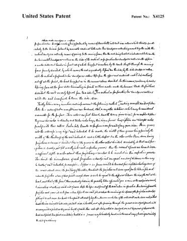
Page 4.
United States Patent
Patent No.: X4125
these side wedges or rollers
perpendicular wedges or rollers being fastened by means of bands belts into each iron rollers which stand perpendicularly to the horizon fastened by movable centers at both ends. These wedges or rollers being moved together with the vertical wedges or rollers by means of gearing to the moving frame, then the rod being heated is introduced between the two horizontal wedges or rollers on the sides of the vertical or perpendicular wedges or rollers on the upper and under sides and headed in front, all of which being put in motion by the crank shaft through the moving frame formerly described, by which means the rod is gradually to pass on the sides, by the side wedges or rollers, while the vertical or perpendicular wedges or rollers take from the upper and under side until it is entirely cut off at the point, the head being put on in the manner above described. In this manner, nails may be made leaving from all the four sides terminating in points as those made under the hammer. Under the first head described the nails are only to work from two sides by two vertical or perpendicular wedges or rollers while the nail is confined between the side sides.
Thirdly, I claim as my invention and improvement the following method of making wrought nails or fish-hooks. Take two rollers of cast or wrought iron case hardened, steel, or any other substance which may be considered answerable for the purpose. These rollers are first turned smooth to any given size, for example, say 1/2 inches in diameter and twelve inches long, their circumference being eighteen and twenty inches (nearly) with these rollers I calibrate to make or prepare iron for nails of any given size. Then grooves into the rollers for every size of nail intended to be made, the width of these grooves being precisely the width of the thickness of the nail intended, and a little deeper. In the other roller I turn down having projections or swages of similar sizes of the grooves in the other roller divided accurately, so that each projection or swage will fit exactly into each respective groove; thus the vacant spaces are turned down a sufficient depth so as to admit these projections or swages to be inserted in their respective grooves. Then divide the circumference of each projection or swage into an equal number of distances as there may be inches of nail intended, for example, suppose a six penny nail to be two and five-eighths inches long, then of the want about twenty the periphery of the roller, then divide the projection into seven equal parts; take a file and reduce the projection at one of these points enough down so as to be equal to the difference between the size of the nail at the head, and that of the point. Thus gradually lessening the quantity taken off, until you arrive at the next point or mark, diminishing at nothing, which will give coarse shape the taper and point off the nail when in operation. Thus having formed the projection and groove, it is a little from a true to form one nail, file or reduce the remaining six spaces of the projection or swage, filling it to a true line heads & two points alternately together. Thus one revolution of the roller will make seven nails without heads. The iron is then cut into sets of suitable sizes, is heated, and after passing through the grooves or swages is formed into as many nails or points as they are in length of nails. These rods after being rolled or swaged are cut by means of shears at the head and point. These points or nails being heated in a furnace may be headed by hand, or in the usual way of heading out nails by the aid of machinery.
Page 5.
United States Patent
Patent No.: X4125
Fourthly, I claim as my invention and exclusive right all the combinations and improvements described under the three former heads, and as there may be an immensity of combinations, or methods combined, whereby wrought nails or spikes may be made by the said machines, the principle being given, which is particularly understood that within they are made by means of grooved rollers having their surfaces or grooves so shaped as to give the required taper to the rod, at each length of nail as is described under the third head. Or whether sections or segments of these rollers or wedges may be taken and fastened into vibrating rollers or wheels. Finishing the nail or spike in one operation, as is described under the first head, all or any of these modes described, or any other combination of the same so long as the nail or spike is shaped by means of rotary or vibrating wedges or rollers, or sections of rollers whose sections or surfaces are so shaped as to give the desired taper to the nail or rod while it is in contact between said rollers or wedges.
Being the first who has ever made wrought nails or spikes in this manner, I reserve the same as my exclusive right and privilege in all the methods above described, the wrought nails or spikes are not pressed smaller under the hand than the body of the nail but is the full size similar to those made by the hand. I use a counter sunk hole in the end of the header which makes the head of the nail or spike high on the center as those made by the hammer.
This latter invention I do not claim farther than the application to my method of making nails.
Henry Borden.
Witnesses
Elam Buck
Robert Christie.
(?? ?? ??)
(Patent is issued on or about 23rd 1839 - Examined by H.L.)
About this record
- Patentee
- Jim Shaw's X-patent list
- Date
- the Name and Date index of patents, USPTO records, Jim Shaw's X-patent list
- Invention
- the Name and Date index of patents
- Listed in
- the Name and Date index of patents, USPTO records, Jim Shaw's X-patent list, S. A. Elliot's printed list of patents, Burke's List of Patents (1847)
- S. A. Elliot's printed list of patents gives the same name and date.
- Burke's 1847 Patent Office list gives the same patent.
- Residence from Burke's 1847 Patent Office list; the standard lists give none.