

Drawings and documents
USPTO scan
The patent as scanned by the USPTO
-
 Page 1
-
 Page 2
-
 Page 3
-
 Page 4
-
 Page 5
-
 Page 6
-
 Page 7
-
 Page 8
-
 Page 9
-
 Page 10
-
 Page 11
-
 Page 12
-
 Page 13
-
 Page 14
-
 Page 15
-
 Page 16
-
 Page 17
-
 Page 18
-
 Page 19
-
 Page 20
-
 Page 21
-
 Page 22
-
 Page 23
-
 Page 24
-
 Page 25
-
 Page 26
-
 Page 27


U.S. Patent and Trademark Office · Google Patents
Show the transcription Hide (7,862 words)
Machine transcription (LightOnOCR) of the pages as scanned by the USPTO, most of them the handwritten copies made when the records were restored after the 1836 fire. Not checked; it can misread handwriting, so compare it with the scan.
Page 2.
United States Patent
Patent No.: X4348
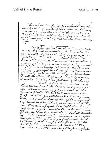
The schedule referred to in these Letters Patent and forming part of the same, containing a description in the words of the said Daniel Treadwell himself of his improvement in the machine for printing called the Power Printing Press.
To all persons to whom these presents shall come, Daniel Treadwell of Boston, in the Commonwealth of Massachusetts Engineer, sends Greeting: Be it known that I the said Daniel Treadwell have invented, constructed and applied to use, a new useful improvement in printing whereby I obtain all the operation necessary for striking impressions from a single rotary motion which improved machine I call the Power Press and which I proceed to describe in this and the following sheets.
I wish it to be borne in mind by the reader, that this machine has a general resemblance in many parts, such as the frames, platen &c. to the common wooden press. As these constitute no part of my invention, no further description of them is necessary, than to show the manner in which they are altered, in form, to adapt them to my improvements. In order to make my invention more clearly understood, I shall describe the whole machine in divisions made from the operations which are performed in the following order.—1st The frame—2d The parts producing the impression. 3d Parts connected with running the form of type.
Page 3.
United States Patent
Patent No.: X4348
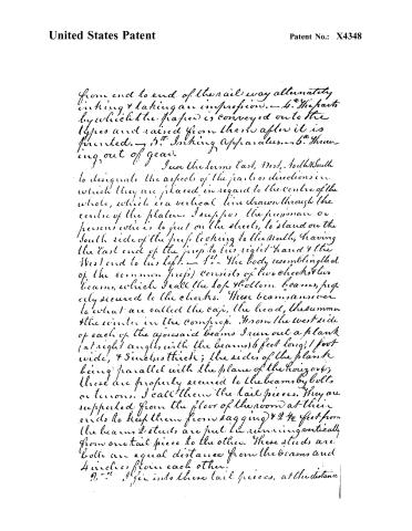
from end to end of the rail way alternately
inking & taking an impression.—4. The parts
by which the paper is conveyed on to the
types and raised from them after it is
printed.—5. Inking Apparatus.—6. Throwing
out of gear.
I use the terms East, West, North, South
to designate the aspects of the parts or directions in
which they are placed in regard to the centre of the
whole, which is a vertical line drawn through the
centre of the plates. I suppose the person or
persons who is to put on the sheets, to stand on the
South side of the press looking to the North, having
the East end of the press to his right-hand & the
West end to his left.—1st—The body resembling that
of the common press) consists of two cheeks & two
beams, which I call the top & bottom beams, properly
secured to the cheeks. These beams answer
to what are called the cap, the head, the summer
& the winter in the common press. From the west side
of each of the aforesaid beams I run out a plank
(at right angles with the beams) 6 feet long, 1 foot
wide, & 3 inches thick; the sides of the plank
being parallel with the plane of the horizon;
these are properly secured to the beams by bolts
or tenons. I call them the tail pieces. They are
supported from the floor of the room at their
ends to keep them from sagging) & 2 ½ feet from
the beams 2 studs are put in running vertically
from one tail piece to the other. These studs are
bolted an equal distance from the beams and
4 inches from each other.
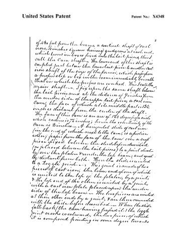
2. The pin into these tail pieces, at the distance
Page 4.
United States Patent
Patent No.: X4348
of 454 feet from the beams, a vertical shaft of cast iron, 4 inches square having gudgeons at each end, which turns in boxes fixed into the tail pieces, this I call the Cam shaft. — The lower end of this shaft is coupled just below the lower tail piece to another cast iron shaft of the size of the former, which passes from a proper step or box in the room immediately beneath that in which the presses are worked. This I call the main shaft. — I fix upon the same shaft between the tail pieces and at the distance of 9 inches from the under side of the upper tail piece, a cast iron Cam, the face of which at its middle part is 13½ inches distant from the center of the shaft. The face of this Cam is an arc of 120 degrees of a circle whose radius is 7½ inches; hence the eccentricity of the Cam is 2 inches. — A horizontal slide of cast iron (in the end of which next to the Cam, is a friction roller) passes from the face of the Cam over a cup piece fixed between the studs before described (as placed between the tail pieces) to a point directly over the platen under the top beam; and equally distant from both. There the slide is united to a toggle joint. — This joint is made of two pieces of cast iron; the lower end of one of which is united to the top of the platen, by a joint; & the top end of the other is united by a joint, with a cast iron plate placed upon the under side of the top beam. — The two pieces are united at their other ends by a joint; & are there connected with the slide before described. — When the slide falls back (the cam having passed it) the toggle joint crooks westwards, the two pieces of which it is composed pointing in some degree towards
Page 5.
United States Patent
Patent No.: X4348
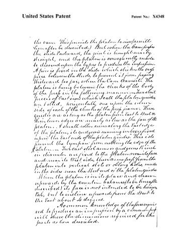
the cam. This permits the platen to rise (as will hereafter be described.) But when the cam pushes the slide Eastward, the joint is brought nearly straight, and the platen is consequently made to descend upon the types to produce the impression. A pin is fixed in the slide which strikes the crop piece between the studs, to prevent it from passing Westward too far, when the cam leaves it. The platen is hung between the cheeks of the body of the press in the following manner: Two stout pieces of cast iron which I call the platen guides, are bolted, horizontally one upon the inner side of each of the cheeks of the press frame. These guides are as long as the platen from East to West, & their lower edges are nearly as low as the face of the platen. A small roller runs along the East edge of the platen, its guide is running in boxes fixed upon the East ends of the platen guides. This is to prevent the tympan from rubbing the edge of the platen. Two cast-steel arms or guides 1 inch in diameter are fixed to the platen near its face and near its West side, these arms pass from the platen into vertical slots or oblong holes, made in the sides near the West end of the platen guides. When the platen is in its place and drawn upwards by the counter-balances (to be hereafter described) its face is not intended to be horizontal, but to incline upwards from the West to the East about 4 degrees.
A common knowledge of the force required to produce an impression by a common press will show the dimensions required for the parts as here described.
Page 6.
United States Patent
Patent No.: X4348
The platen is counterbalanced by weights pivoted to levers upon the upper side of the top beam & connected with the platen by rods passing through holes in the top beam & united with the platen between the centre of gravity, and its arms or quodgeons. The weight of the counter-balance should be enough to keep the platen always pressed against the toggle joint.
The operation of these parts concerned in producing the impression is as follows: The cam shaft being made to revolve from East to South the cam strikes the roller in the end of the slide which being prevented from passing southward by a friction roller on the South side between the tail pieces, the slide is wedged or pushed Eastward by the cam. This tends to straighten the toggle joint & consequently to make the platen descend, (the bed & types & sheet to be printed being by the general term of the press to be hereafter described more under the platen) the impression is made. From the manner of counterbalancing the platen (the weight acting between the centre of gravity of the platen & its quodgeons or arms at its West side) the East edge of the platen descends first, when this touches the types & is thereby resisted, the West side descends, the quodgeons slipping down into the slots, in which they are hung. The whole descent of the platen should be its East edge about 2 inches, and its West edge about ½ an inch. After the full part, or centre of the cam, has passed the slide, the reaction of the beam and other parts together with the counterbalance of the platen, causes the platen to rise as the cam passes onward, and the toggle joint to cock backwards; the slide following
Page 7.
United States Patent
Patent No.: X4348
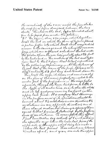
the eccentricity of the cam until the pin strikes the crop piece before described, between the two studs. This leaves the bed, types & printed sheet free to be passed from under the platen.
3. The coffin, stone & carriage, which together I call the bed on which the form of types is placed is put on proper rails which I call rail ways which answer to the carriage and the rails of the common press, which are so placed as to direct the bed under the platen & from thence horizontally about 3½ feet to the Eastward. The motion of the bed and types from East to West, & from West to East, is produced by the following Machinery. At the distance of 1½ foot West of the beams of the press, I place a round shaft vertically 4½ feet long and 1½ inch diameter. This I call the verge, its lower end runs in a step on the floor of the room, properly connected to the under part of the press frame. The verge passes upwards, through the lower tail piece, a little to the North of its centre line, so as to clear the slide, and its top guide runs in box fixed in the upper tail piece. It is necessary that this verge in the performance of its operations, should be turned about 2½ revolutions in one direction, 2½ revolutions in an opposite direction, and then stand motionless during a space of time equal to that previously taken up by the performance of revolutions. To accomplish this effect, I put two Mitre cog wheels of 8 inches diameter upon the verge below the lower tail piece (the upper side of the upper wheel being two inches below the tail pieces) These wheels are placed 8 inches apart, and gear, one into the other.
Page 8.
United States Patent
Patent No.: X4348
5:
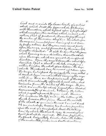
limb and one into the lower limbs, of a vertical wheel, which I call the jam wheel, of like size with themselves, which is fixed upon a proper shaft which runs from this vertical wheel, in such a direction, that if produced, it would pass through the centre of the main shaft. The wheels upon the verge are prevented from moving up and down by proper collars; but they can move round freely upon the verge, unless prevented by the means to be hereafter described. It will be seen that the jam wheel turning in one direction, drives the wheels upon the verge, which are geared to it, in opposite directions. Upon the verge between the wheels before described, I put a chuck or clutch, occupying within 2 inches, the whole space between the verge wheels. This chuck can be moved up & down upon the verge, but is fixed by wings to the verge so that it cannot turn round without carrying the verge with it. There are two pins in each of the verge wheels diametrically opposite to each other, and two inches from the centre of the verge. The pins which are in the top wheels project from the wheel downwards, 3/4 of an inch, & those in the bottom wheel project upwards 3/4 of an inch. There are slots made in the top, and in the bottom of the chuck to receive these pins. Round the middle of the chuck a groove is turned to an inch broad & 1/2 an inch deep, to receive two knobs or projections upon the end of a lever, which I call the locking lever by which the chuck may be moved up and down as shall be required. This lever passes from the chuck horizontally 6 inches below the bottom of the under tail pieces, in a south direction,
Page 9.
United States Patent
Patent No.: X4348
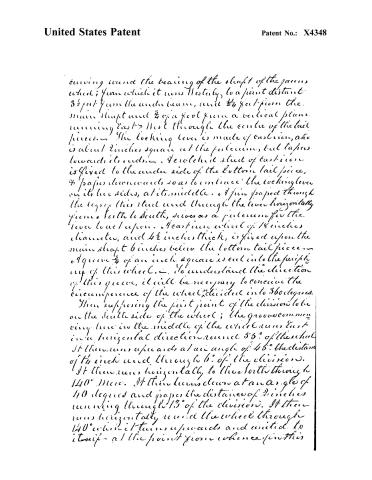
running round the bearing of the shaft of the gears wheel; from which it runs Westly, to a point distant 3½ feet from the under beam, and ¾ foot from the main shaft and ¾ of a foot from a vertical plane running East to West through the centre of the tail pieces. The locking lever is made of cast iron, and is about 2 inches square at the fulcrum, but tapers towards its ends. A perforated stud of cast iron is fixed to the under side of the bottom tail piece, ¾ paper downwards so as to embrace the locking lever on its two sides, at its middle. A pin passed through the top of this stud and through the lever horizontally from South to South, serves as a fulcrum for the lever to act upon. A cast iron wheel of 18 inches diameter, and 4½ inches thick, is fixed upon the main shaft 6 inches below the bottom tail piece. A groove ¼ of an inch square is cut into the periphery of this wheel. To understand the direction of this groove, it will be necessary to conceive the circumference of the wheel divided into 360 degrees. Then supposing the first point of the division to be on the South side of the wheel; the groove commencing here in the middle of the wheel runs East in a horizontal direction round 55° of the wheel. It then runs upwards at an angle of 45° the distance of ½ inch and through 6° of the division. It then runs horizontally to the North through 140° more. It then turns down at an angle of 40 degrees and passes the distance of 2 inches running through 13° of the division. It then runs horizontally round the wheel through 140° which it turns upwards and united to itself at the point from whence it started.
Page 10.
United States Patent
Patent No.: X4348
Description
I have supposed it to commence making one uninterrupted, but crooked channel round the whole circumference of the wheel. A lever which I call the groove lever, tapering on the south side of the locking lever to which it is fixed by a proper joint—finches West of the fulcrum of the locking lever. This joint permits the groove lever to move in the plane of the horizon about 5 degrees. The Western end of the groove lever passes by the Western end of the locking lever, turning at an angle directly across this last, towards the center of the groove wheel, the groove of which it enters passing nearly to its bottom. The Eastern end of the groove lever is produced horizontally, under the lower tail piece, until it nearly meets the West side of the lower great beam. A small iron lever is fixed to the great beam in the horizontal plane of the groove lever by a round pin through its middle part. This lever is crooked at its middle, and one arm points to the South, while the other points directly upwards. From this last part, a rod or chain passes to the South to attach it to the groove lever, and a weight is hung from its other arms, by this means the East end of the groove lever is always pulled by the weight to the South, and the West end kept in the groove. Under the groove wheel, and fixed upon the main shaft, is a level cog-wheel, the cogs pointing upwards, 2 7/2 feet diameter, and having 132 teeth. This is a horizontal wheel and it drives a vertical jack having 22 teeth, which is fixed upon the Western end of the shaft of the yawmwheel.
Page 11.
United States Patent
Patent No.: X4348
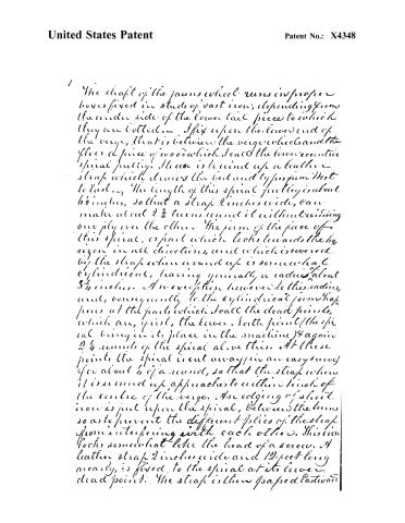
The shaft of the jaws wheel runs in proper boxes fixed in studs of cast iron, depending from the under side of the lower tail piece to which they are bolted. I fix upon the lower end of the verge, that is between the verge wheels and the floor a piece of wood which I call the lower eccentric spiral pulley. There is wound up a leather strap which drives the bed and type from West to East. The length of this spiral pulley is about 6½ inches, so that a strap 2 inches wide, can make about 2¾ turns round it without crossing one ply over the other. The form of the face of this spiral, or part which looks towards the horizon in all directions, and which is covered by the strap when wound up is somewhat cylindrical, having generally a radius about 3½ inches. A mere exception however to this radius, and, consequently, to the cylindrical form that prevails at the parts which I call the dead points, which are, first, the lower North point (this spiral being in its place in the machine) & again 2¼ rounds of the spiral above this. At these points the spiral is cut away in an easy curve of about ¼ of a round, so that the strap when it is wound up approaches to within 1 inch of the centre of the verge. An edging of sheet iron is put upon the spiral, between the turns so as to prevent the different plies of the strap from interfering with each other. This iron looks somewhat like the head of a screw. A leather strap 2 inches wide and 12 feet long nearly, is fixed to the spiral at its lower dead point. The strap is then passed Eastward
Page 12.
United States Patent
Patent No.: X4348
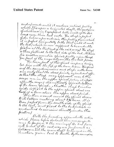
and upwards until it reaches a vertical pulley which I fix upon a horizontal shaft, the guides of which are in boxes fixed to the inside of the rail ways near their East ends. The strap is passed from below upwards over this pulley from which it is passed horizontally to the West until it meets the bed (which is now supposed to be under the platform at the West end of the rail way.) The strap is then fastened to the East side of the bed. I likewise fix another eccentric spiral pulley upon the upper part of the verge between the two rail pieces.
The lower part of this spiral is upon a horizontal line with the top of the lower beam. This spiral is of the same dimensions and shape as the lower one only that the dead points, or parts out off, so that the strap may approach near to the verge are in the upper spiral (when it is fixed upon the verge) diametrically opposite to those of the lower spiral. I fix the strap 2 inches wide is fixed to the upper spiral about one half of a turn above the upper dead point.
It is then wound round the spiral down to its bottom making about 2¾ turns. It is then passed from the south side of the spiral to the East, and fixed to the bed (which is understood to remain directly under the platform.)
With the preceding apparatus the motions which I have before declared were necessary for the verge to perform & the moving of the bed from end to end of the rail way are performed as follows. — Let the main shaft be turned in the direction from East to South. By the connexion
Page 13.
United States Patent
Patent No.: X4348
of the wheel work the two wheels upon the verge are driven round, the top one from East to South and the bottom one from South to East. Suppose now, that the end of the groove lever, is in the shortest of the horizontal parts of the grooves, that the locking lever is therefore horizontal in direction, and the chuck, between the verge wheels equidistant from each of these wheels and consequently not locked by the pins either of them. — On the further revolution of the groove wheel, the part of the groove which crooks upwards, arrives at the end of the groove lever and forces the West end of the locking lever upwards and, consequently its East end downwards which carries the chuck with it. The pins in the lower verge wheel, then fall into the slots in the chuck, the chuck is carried round by the lower verge wheel and carries with it the verge. This carries the lower dead point of the lower eccentric spiral pulley, to which the lower strap is fixed, from South to West, winding up the strap, and consequently pulling the bed from West to East, the upper spiral unwinding its own strap as fast as the lower spiral winds up. Having made 2½ revolutions the grooves will have arrived at the part which crooks downwards & passing on will force the West end of the locking lever downwards, & its East end upwards. — This carries the chuck on the verge up, releasing the pins of the lower wheel and locking into those of the upper one, which turning in an opposite direction, reverses the direction of the revolutions of the verge. By this
Page 14.
United States Patent
Patent No.: X4348
operations the winding and unwinding of the strap, is also reversed so that the bed which has been carried about 3 7/8 feet to the East, is, now—by the winding up of the upper strap returned from East to West & carried under the platform. The verge having made 2 1/4 revolutions in this new direction, the last angle of the groove will have arrived at the end of the groove lever which will force the West end of the locking lever upwards & the East end downwards far enough to slip the chuck from the pins of the upper verge wheel. The verge then rests & also the bed and its appendages, until the shortest of the horizontal parts of the groove has passed over the end of the groove lever which by my dimensions is equal to $\frac{56}{360}$ of a revolution of the groove wheel. The same operations are then repeated.
All these motions have a certain relation to each other in the order of succession in which they take place, and likewise a relation to the time in which the impression is given. In order to produce the motion in their regular times and relations it is necessary to place the groove wheel upon the main shaft in such a manner that the shortest horizontal part of the groove, may just arrive at the end of groove lever at the moment that the cam first presses upon the impression slide. And it is likewise necessary to lock the teeth of the gear wheel to those of the verge wheels, in such parts of their circumference, that the pins in the verge wheels shall be at the proper place to slip into the slots in the chuck of the verge when the chuck is moved up & down by the operation of the apparatus attached to it.
Page 15.
United States Patent
Patent No.: X4348
4. The paper is conveyed to its place for the impression by the following apparatus. I make two slides, which I call the pusher slides, 1/2 foot long, 1 inch wide & 3/8 inch thick of iron. These I place horizontally with the edges looking up and down, one upon the North & one upon the South side of the bed. Two pieces of iron having an oblong hole in each, being fixed to the bed to receive the slides. These slides, can thus slip in the holes or boxes in which they are placed 2 1/2 feet from East to West or contrary-wise. To the West end of each of these slides, I rivet two pieces of iron 3/4 inches long 1 inch wide and 3/8 inch thick. These pieces point upwards from the slides at a right angle, and their tops rise 1 1/2 inch above the upper face of the bed. I make through each of these pieces of iron 1 inch above the face of the bed, a hole 1 inch in diameter. Having made a frame of iron which I call the pusher and which is of the size & shape of the pusher of a common printing press, I fix to two of its corners on the same slide, two guides about 2 inches long. These I put into the holes before described in the ends of the slides. I now suppose the slides run to the East until their end pieces strike the iron on the West side of the bed, and (supposing the form of types to be in its place upon the bed) the pusher can now be let down so as just to cover the chase, the several sides of which are round and parallel to the corresponding sides of the pusher. To each of the East corners of the pusher, I run out to the North & South a piece of iron 3 inches long and 3/8 inch square, which
Page 16.
United States Patent
Patent No.: X4348
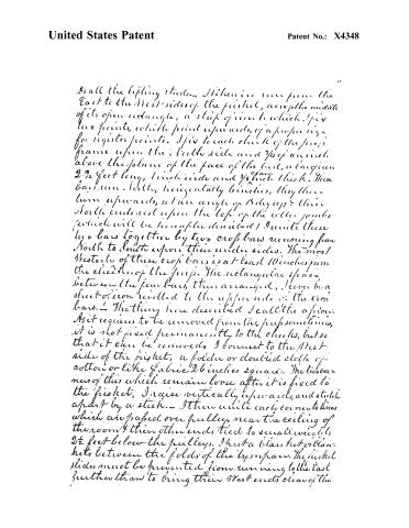
I call the lifting sticks. I have here two from the East to the West sides of the pisket, across the middle of its open rectangle, a strip of iron to which I fix two points, which point upwards, of a proper size for register points. I fix to each check of the pisket frame upon the North side and 3/4 of an inch above the plane of the face of the bed, a bar, 2-3/2 feet long, 1 inch wide and 3/8 inch thick. These bars run North, horizontally, they then turn upwards, at an angle of 15 degrees, their North ends rest upon the top of the roller junks (which will be hereafter described). I unite these two bars together by two cross bars running from North to South upon their under sides. The most Westerly of these cross bars is at least 10 inches from the checks of the pisket. The rectangular space between the four bars, thus arranged, I cover by a sheet of iron rivelled to the upper side of the cross bars. The thing here described I call the aforesaid. As it requires to be removed from the pisket sometimes, it is not fixed permanently to the checks, but so that it can be removed. I connect to the West side of the pisket, a folder or doubled cloth of cotton or like fabric 26 inches square. The two corners of this which remain loose after it is fixed to the pisket, I raise vertically upwards, and stretch apart by a stick. I then unite each corner to lines which are passed over pulleys, near the ceiling of the room, and their other ends tied to small weights 2½ feet below the pulleys. I put a blanket or blankets between the folds of the byspars. The pisket slides must be prevented from running to the East further than to bring their West ends clear of the
Page 17.
United States Patent
Patent No.: X4348
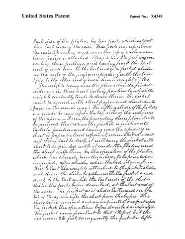
East side of the platen, by two posts, which support the East ends of the rails. These posts run up above the rails 4½ inches, and near the top of each a vertical pulley is attached. I lay a line 2½ feet long over each of these pulleys, and having fixed the West end of each line to the East end of a ficket slide on the side of the press corresponding with the line I fix to the other end of each line a weight of 7 lbs.
The weights hang near the floor when the ficket slides are in their most Easterly position to which the weights constantly tend, to draw them. The ficket must be covered with stout paper and divided into pages in the usual way. The lifting studs (of the ficket) are made to run upon the top side of the side pieces of the apron. — From the preceding description it will be perceived that when the ficket is in its most Easterly position and laying over the apron if a sheet of paper be laid upon it, when the bed is carried from East to West, it will carry the ficket and sheet to be printed with it under the platen, and the sheet will there, by the operation of the platen which has already been described, to be printed or imprinted, after which, when the bed returns from West to East the weights attached to the ficket slides, will draw the slides together with the ficket and sheet, to the East until the East ends of the slides strike the posts before described, at the East-end of the rails. The ficket as it slides Eastward on the top of the apron lifts the sheet from the types. The sheet being removed and an unprinted one put upon the ficket, the operations before described are repeated. The ficket moves from East to West 1½ feet; but the bed moves 3½ feet; consequently the ficket is left-
Page 18.
United States Patent
Patent No.: X4348
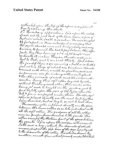
motion upon the top of the apron a sufficient time to exchange the sheets.
5th. The inking apparatus.—I fix upon the outside of each rail 1½ feet East of the lower beam, a piece of Cast Iron which I call a jamb. The rails being but 2½ feet apart in their outside it is necessary that the jambs should run out horizontally each way 2 inches, to permit the bed to pass between their upper parts. They then turn up at a right angle & rise vertically 12 inches. They are 12 inches wide from East to West, and 2 inches thick. I put between the jambs of their axis running a North and South) four rollers, three of which are 3 inches in diameter & covered with skin, or with composition, such as is in common use for inking rollers in England. & the other is made of wood and 2½ inches in diameter. Two of these soft rollers lay side by side, without touching each other, their under sides being at such a height in the jambs as just to press lightly upon the face of the types, when the bed & form are passed under them. The other soft roller is placed directly over the most Easterly of those before described, but so high as not to touch them.
The wooden roller is placed directly over the space between the lower rollers so as to be in contact with all the soft rollers. The guides of all the rollers run in proper boxes screwed to the jambs. The rollers occupy the Western part of the space between the jambs. I fix upon the wooden roller near its North end a cog-wheel the diameter of which measured upon the dip line of the cogs is just equal to the diameter of the roller. This wheel is driven by another small spur wheel (nearly under it) which
Page 19.
United States Patent
Patent No.: X4348
turns upon a pin fixed upon the inside of the North jamb. The last described wheel is turned by a rack 5 feet long, the teeth of which point upwards, fixed upon the North side of the bed. The rack is fixed by such a part of it to the bed, as to bring its East end nearly under the western roller, when the bed is under the platen, and its West end when the bed is in its most Easterly position.— The ink is supplied from a fountain which has the appearance of an iron box 2½ feet long and 2 inches deep and 3 inches wide, the top & West side being taken off and an iron roller supplying the place of the West side.— This iron roller is 2 feet long between the quillgears and 2 inches in diameter and it is placed against the iron box or body of the fountain so that a horizontal plane, passing through its axis will intersect the bottom of the box or fountain. The quillgears of the fountain roller here described revolve in the ends of the iron box or body of the fountain, a cap upon their West sides keeping them in place.
These ends pass downwards below the roller 4 inches. Near the bottom of each, an arm is fixed passing outwards both ways. The ends of these arms are formed into quillgears, which are placed in holes, one in each jamb, & constitute the axis on which the fountain can be rolled through a small arc from East to West— Thus, the fountain occupies the space between the jambs East of the inking rollers, & it is put at such a height between the jambs, that a plane drawn horizontally through the axis of the uppermost inking roller, will pass through the axis of the fountain roller.— The space between the West side of the fountain roller, and the East side of the upper inking roller is (when the fountain is back or in its most Easterly
Page 20.
United States Patent
Patent No.: X4348
positions about 1 inch, the rollers having parallel to each other. The fountain thus described is like those used upon the English printing machine invented by Mr. Rutt. I fix upon the south end of the guide-iron of the fountain roller which projects beyond the end of fountain to receive it in a ratchet or rag wheel. A proper pull or dog hand is fixed upon the south rails so as to fall into the notches upon the top of the rag wheel. The standing parts of the notches upon the top of the rag wheel look towards the West, and the notches stand to the East in the direction of the chord of an arc. An iron bar is firmly fixed to the arm which runs from the south end of the fountain to the south rails; this bar runs from the arm downwards, nearly to the plane of the top of the rails. An iron slide passes from the above described bar at its West side and near its lower end, Westerly through the lower South corner of the open rectangular space, comprised between the cheeks and beams of the press frame, to the West side of the lower beam & projecting West of it about 2 inches. The West end of this slide is covered by another iron bar which I call the vertical hinge which passes from it downwards, & is fixed by a hinge joint to the press frame near the floor. Another iron bar which I call the horizontal hinge, is fixed by a screw bolt passing through its end, and likewise through the vertical hinge near its middle from whence the horizontal hinge passes Northerly over the top of the lower tail piece to meet the end of the lower beam of the frame to which it is fixed by a hinge joint.
Page 21.
United States Patent
Patent No.: X4348
A slide runs from the West side of the horizontal hinge just over the upper side of the lower tailpiece, until it almost reaches the Cam Shaft. A steel pin projects from the Cam Shaft in a line directly under the Cam and at such a point that when the Cam revolves the pin will push the last described slide to the East. The slides are prevented from moving laterally by proper braces fixed upon the lower beam and the lower tailpiece.
An important part of the writing apparatus is the revolving table. Fixed to the East side of the bed, a light frame of iron which runs out from the bed 14 feet to the East. The upper side of the frame is 2½ inches below the face of the bed from which it is properly braced. The revolving table is 28 inches in diameter. It is made of wood and its upper face is a circular disk. A round iron axis 1 inch in diameter passes downwards from its centre 6 inches. This axis passes through a vertical hole near the Easterly part of the frame just now described as fixed to the bed. A shoulder is turned upon the upper part of the axis which rests upon the upper side of the frame, & prevents the table from falling down too low. When the table is in place its upper face should be horizontal, & just as high as the face of the type upon the bed. A light ring wheel 18 inches in diameter is fixed upon the under side of the revolving table ¼ inch below it and parallel and concentric with it. A dog hand or catch is fixed to one of the rails of the frame by a hinge joint in such a place and position that it will catch into the teeth upon the side of the ring wheel when the bed and consequently the revolving table is brought into its most Easterly position. The dog hand or catch is brought so as
Page 22.
United States Patent
Patent No.: X4348
to catch the teeth by a spring and prevented from
popping too far by a stop received upon the piece
frame.
I understand the manner in which the inking
apparatus operates, we will suppose that the fountain
is filled with ink, that the roller and top of the inking
table are covered with a thin coat of it, & that
the beam shaft is made to revolve & consequently the bed
& types, to take up a reciprocating motion upon the
rail way. When the steel pin in the beam shaft,
strikes the slide (belonging to the inking apparatus)
and drives it to the East. This brings the top of the
inking fountain to the West, but as the pull upon
the double jambs prevents the top of the rag-wheel
on the fountain roller from moving with the fountain,
the fountain roller is constrained to turn round a
few degrees upon its axis. By this means some of
the ink which adheres to the roller, is carried with
it out of the fountain in a thin sheet (the remainder
being kept in the fountain by the iron bottom.) During
this operation the fountain, passing to the West, brings
the fountain roller in contact with the uppermost
inking roller & in this manner the inking rollers
are supplied with ink. When the bed begins to pass
to the Eastward, the inking rollers by reason of their
connection by the cog-wheels, as before described, with
the rack, are made to revolve, the undersides of the
two lowermost ones passing towards the East. They
are at first in contact with the revolving table, but
after the bed & table have passed over part of the rail-
way they come in contact with the types & impart
some of the ink from their surface to the face of the
letter, and a still further quantity when the
Page 23.
United States Patent
Patent No.: X4348
bed passes from East to West. When the bed & table are at their most Easterly positions, the catch, which has been described as hinged to the rail way, catches into the ray-wheel fixed upon the under side of the revolving table and when the table returns to the West this causes it to revolve in a greater or less degree.
By this means when the table comes again in contact with the inking rollers, the points which before came in contact with certain points of the rollers, come now in contact with other points. By the above operation the ink is supplied and distributed evenly upon the types.
To get a sufficient quantity of ink upon the rollers on commencing work, it is necessary to let the fountain work without taking impressions. After this the fountain roller supplies each time it comes in contact with the inking rollers as much ink as is taken off by inking the types. The fountain may be regulated to supply more or less ink at pleasure by screwing or unscrewing the caps which keep the fountain roller in its place to the fountain.
b. Moving out of gear, upon the middle of the West side of the lower great beam, I fix a notched piece of cast iron which I call the hold fast, the open part of which resembles in its appearance a boot jack. It is so fixed upon the beam that the two horns point to the South one being directly over the other. The Eastern end of the groove lever (as was said in a former part of this specification) approaches very near the West side of the great beam, and consequently it can be thrust to the North, so as to enter between the horns of the hold fast. I fix upon the West side of the South cheek of the frame, vertically an iron lever 3 feet long its fulcrum being a pin which is put through its
Page 24.
United States Patent
Patent No.: X4348
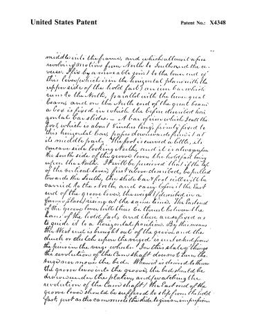
middle into the frame, and which allows it a free revolving motion from North to South and the reverse. This is by a moveable joint to the lower end of this lever (which is in the horizontal plane with the upper side of the bolt fast) an iron bar which runs to the North, parallel with the lower great beam, and on the North end of the great beam a box is fixed in which the before described horizontal bar slides. — A bar of iron which I call the foot, which is about 8 inches long, firmly fixed to this horizontal bar, projects downwards from it at its middle part. The foot is curved a little, its concave side looking North, and it is always upon the South side of the groove lever, the bolt fast being upon the North. It will be perceived that if the top of the vertical lever, first above described, be pulled towards the South, the slide bar & foot will be carried to the North, and carry before it the East end of the groove lever, the weight (described in a former place) rising at the same time. The East end of the groove lever will thus be thrust between the bars of the bolt fast, and these are so fixed as to guide it to a horizontal position. By this means the West end is brought out of the groove and the chuck or clutch upon the verge is unlocked from the pins in the verge wheels. In this state of things the revolution of the Cam shaft does not turn the verge nor move the bed. When it is desired to throw the groove lever into the groove, the bed should be drawn under the platen, and (watching the revolution of the Cam shaft) the East end of the groove lever should be suffered to slip from the bolt fast, just as the cam meets the slide to give an impression.
Page 25.
United States Patent
Patent No.: X4348
A lever is hung directly under the ceiling or roof of the room, by a movable joint near its middle. The West end of this lever is directly over the slide which passes from the beam to the toggle joint, and is fixed to it at a point 1 foot from its West end, by a rod or chains, the East end of the lever is brought directly over the left hand of the prep. — I have having a proper handle hangs down from this end of the lever. — Nothing more is required than to pull the above rod downwards, (when it is required to stop taking in prep.) this raises the Western end of the slide higher than the face of the beam, which therefore passes under it without thrusting it forward. The slide is kept out of its working place by hooking the aforesaid rod to a pin in the South cheek of the prep.
In the foregoing specification I have described a great variety of wheels, levers, slides, & other instruments which are common elements in all machines. I do not pretend to have invented these, & hereby except them in their individual & simple characters, out of my claim for a patent. Neither do I claim a patent for the plates, the bed, the rails, the forket, the inking rollers, the ink fountain or the body or frame of the prep. Neither do I claim a patent for making any of the parts of certain materials, or of certain sizes, as they may be varied without altering the character of my invention. Some of the subordinate combinations, herein described are not new, such as the combination of the toggle joint & plates, that of the verge and those which connected with it. — These therefore make no part of my invention.
I will now endeavor to state distinctly in what my invention consists. I understand
Page 26.
United States Patent
Patent No.: X4348
my invention to consist.—
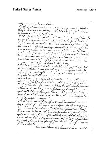
1st of the combination and arrangement of the cam shaft, lemniscate slide, with the toggle joint & plate to produce the impulsion.
2nd I have taken the old combination of the X verge, three wheels, click or clutch, pin & locking lever, and invented a combination of them with the eccentric spiral pulleys, and the bed. And further I have invented a combination of these with the main shaft, and the peculiar groove wheel which I have described, whereby certain necessary motions and certain states of rest are produced in regular succession and for definite periods.
3rd I have invented the combination of the fork with its slide, and the apron, and likewise the peculiar manner of arranging the tympan and blankets with them.
4th I have invented the combination of the rag-wheel with the fountain rollers, and likewise that of the hinges and slides, by which the fountain rollers is turned, and likewise brought into contact with the inkling rollers.— I have likewise combined with the inkling rollers, the revolving table and its appendages.
5th I have invented the combination herein described for throwing certain parts out of gear.
6th I have combined as (heretofore described) the several preceding subordinate combinations into a general combination, in which they all have a certain dependence upon, and relation to, each other, necessary for the due performance of the whole.—
Under these six heads I have stated
Page 27.
United States Patent
Patent No.: X4348
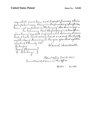
my whole invention, and I except from my claim for a patent every thing in the preceding specification, not embraced in the terms of this summary.— In testimony that the foregoing is a true specification of my said improvement as herein described, I have hereunto set my hand and seal this twenty eighth day of January in the year of our Lord eighteen hundred & twenty six.
Daniel Breadwell.
Witnesses
Jason Braman?
H. Whiting.
Patent Office Decr. 18, 1851
Recorded anew in this Office.
10.056 / Excl. 21
Published accounts: journal notice
Notice in the monthly list of patents
Franklin Journal and American Mechanics' Magazine, vol. 1 (1826), p. 311 · View the page
In the machine for printing, March 2, Daniel Treadwell, Boston.
About this record
- Patentee
- DATAMP
- Date
- the Name and Date index of patents, DATAMP, USPTO records
- Invention
- DATAMP
- Listed in
- the Name and Date index of patents, DATAMP, USPTO records, Jim Shaw's X-patent list, the Journal of the Franklin Institute, S. A. Elliot's printed list of patents, Burke's List of Patents (1847)
- S. A. Elliot's printed list of patents gives the same name and date.
- Burke's 1847 Patent Office list gives the same patent.