

Drawings and documents
USPTO scan
The patent as scanned by the USPTO
-
 Page 1
-
 Page 2
-
 Page 3
-
 Page 4
-
 Page 5
-
 Page 6
-
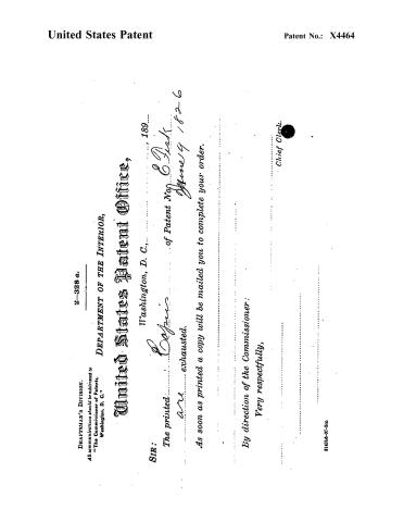 Page 7


U.S. Patent and Trademark Office · Google Patents
Show the transcription Hide (1,768 words)
Machine transcription (LightOnOCR) of the pages as scanned by the USPTO, most of them the handwritten copies made when the records were restored after the 1836 fire. Not checked; it can misread handwriting, so compare it with the scan.
Page 2.
United States Patent
Patent No.: X4464
Ezra Stark and Benjamin Hinkle
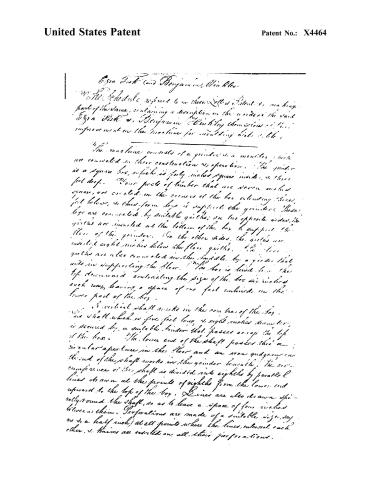
We, the undersigned, do hereby declare that we have invented a new and useful improvement in the machine for moulding bricks, which we now fully describe and claim.
The machine consists of a grinder, a moulder, and a brick maker, all connected in their construction and operation. The grinder is a square box, which is forty inches square inside, and three feet deep. Four pieces of timber that are seven inches square, are erected in the corners of the box extending three feet below, and thus form legs to support the grinder. These legs are connected by suitable girders; on two opposite sides, the girders are inserted at the bottom of the box to support the floor of the grinder. On the other sides, the girders are inserted eight inches below the floor girders. The floor girders are also connected in the middle by a girder that aids in supporting the floor. The box is hinged to the top downward contracting the size of the box as it is raised each way, leaving a space of one foot enclosed in the lower part of the box.
A vertical shaft exists in the center of the box. This shaft which is five feet long, eight inches diameter, is secured by a suitable binder that passes across the top of the box. The lower end of the shaft passes through a circular aperture in the floor and an iron gudgeon on the end of the shaft works in the grinder beneath. The circumference of the shaft is divided into eighths by parallel lines drawn at the points of eighths from the lower end upward to the top of the box. Lines are also drawn spirally round the shaft, so as to leave a space of four inches between them. Perforations are made of a suitable size, say one to a half inch, at all points where the lines intersect each other, and knives are inserted in all their perforations.
Page 3.
United States Patent
Patent No.: X4464
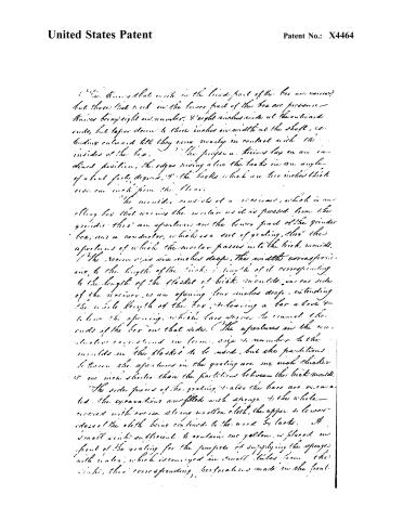
It is known that the walls in the lower part of the box are narrow, but those that are in the lower part of the box are pressure—thick being eight in number, 8 eight inches wide at the outward ends, but taper down to three inches in width at the shaft, extending outward till they come nearly in contact with the insides of the box. The pressure thins lay on an inclined position, the edges rising above the backs in an angle of about forty degrees, and the backs which are two inches thick rise one inch from the floor.
The moulds consist of a receiver, which is an ellipsoidal box that receives the mortar as it is pressed from the grinder; there are apertures in the lower part of the grinder box, and a conductor, which is a sort of grating, through the apertures of which the mortar passes into the brick moulds. The receiver is six inches deep, the width corresponding to the length of the brick; length of it corresponding to the length of the flasket of brick moulds. In one side of the receiver is an opening four inches deep, extending the whole length of the box, to leaving a bar above and below the opening, which bars serve to connect the ends of the box on that side. The apertures in the conductor correspond in form, size & number to the moulds in the flasket to be used, but the partitions between the apertures in the grating are one inch thicker or one inch shorter than the partitions between the brick moulds.
The side pieces of the grating, and also the bars are excavated. The excavations are filled with sponge & the whole covered with coarse strong woollen cloth, the upper & lower edges of the cloth being confined to the wood by laces. A small cistern sufficient to contain one gallon, is placed in front of the grating for the purpose of supplying the sponge with water, which is conveyed in small tubes from the cistern, through corresponding perforations made in the front.
Page 4.
United States Patent
Patent No.: X4464
pieces of the grating. — (The pressure of the water as it passes through the grating causes the water to surge out through the slots, which facilitates the discharge of the bricks from the mounds. The grating may be used with or without the change according to the clay shall require. — To connect the moulder with the grinder, the conductor is attached to one side, or it may be attached to two opposite sides of the grinder, resting upon arms which extend outward from the body of the grinder. — (The grating is so stationed that the upper side of it falls in about a half below the upper side of the floor of the grinder. The receiver sits upon the grating, the open side coming in close contact with the side of the grinder; the opening in the side of the receiver corresponding exactly to a like opening made in the side of the grinder at the bottom. The grating is secured in its place by iron bolts that pass through the front pieces, the arms on which it rests. The receiver is confined in its place by a tie at the ends which confine it to the grating. To work the mounds they are placed on a slide that works horizontally under the grating. This slide is a square frame not about thirty inches long, and twenty inches wide. A floor, fifteen inches wide, is placed upon that end of the slide which works under the machine, the upper side of the floor forming a level with the upper side of the mounds as they lay in the slide. The slide works on two bed pieces that are confined in the lower joints of the grinder. On the upper sides of these bed pieces are tongues of sufficient length to accommodate the motion of the slide, and these tongues work in corresponding grooves in the under sides of the cross pieces of the slide. The slide is worked by a wheel that is fifteen inches diameter, placed in a vertical position under the the middle of the slide, the shaft of the wheel being supported by arms that extend.
Page 5.
United States Patent
Patent No.: X4464
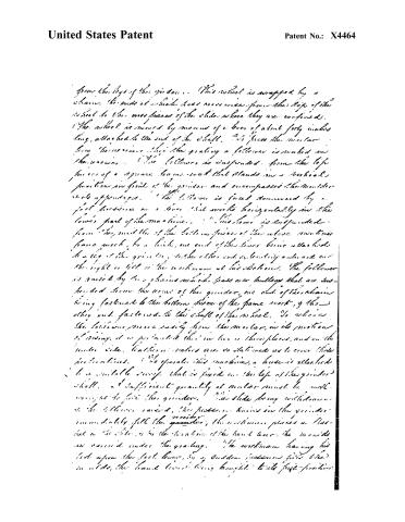
from the legs of the grinder. This wheel is wrapped by a chain, the ends of which pass over one from the top of the wheel to the cross pieces of the slide where they are confined. The wheel is moved by means of a lever of about forty inches long, attached to the end of the shaft. It is fixed the motor from the center of the grinding a follower is mounted in the power. The follower is suspended from the top pieces of a square frame work that stands in a vertical position in front of the grinder and encompasses the motor and its apparatus. The follower is forced downward by a foot pressure on a lever that works horizontally in the lower part of the machine. The lever is suspended from the mid of the bottom pieces of the above mentioned frame work, by a link, one end of the lever being attached to a leg of the grinder, while the other end is leaning outward on the right or left of the workman at his station. The follower is raised by two chains which pass over pulleys that are suspended from the arms of the grinder, one end of the chains being fastened to the bottom pieces of the frame work, and the other end fastened to the shaft of the wheel. So when the follower moves easily from the motor, in its motion of rising, it is prevented thus in two or three places, and on the under side, leather or rollers are so stationed as to cover these positions. To operate this machine, a handle is attached to a suitable sweep that is fixed on the top of the grinder shaft. A sufficient quantity of mortar must be well enough to fill the grinder. The slide being withdrawn, the follower raised, the pressure being in the grinder immediately fill the grinder, the workman places a flat-heel on the slide, and by the rotation of the hand lever, the mortar is carried under the grinding. The workman having his foot upon the foot lever, by a sudden pressure gives the in order, the hand lever being brought to its first position.
Page 6.
United States Patent
Patent No.: X4464
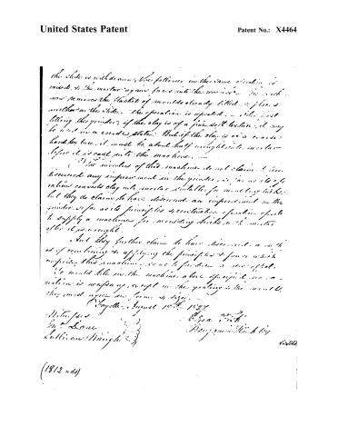
the slide is withdrawn, the follower in the same position is raised, & the mortar again forced into the mortar. The work now removes the flasks of moulds already filled, & places another on the slide. The operation is repeated. — After first filling the grinder, if the clay is of a fine soil texture, it may be used in a crude state. But if the clay is of a coarse hard texture, it must be about half wrought into mortar before it is cast into the machine.
The inventors of this machine do not claim to have discovered any improvement in the grinder, so far as its operations converts clay into mortar suitable for moulding bricks; but they do claim to have discovered an improvement in the grinder, so far as its principles & construction of operation, to supply a machine for moulding bricks with mortar after it is wrought.
And they further claim to have discovered a method of combining & applying the principles & powers which comprise this machine, so as to produce a new effect.
We would like in the machine above specified, no machine is necessary, except in the grinding & the moulds, they must agree in form & size.
Hayes, August 18th, 1827
Wm. T. Jones
J. A. Lane
William Wright
E. G. A. Smith
Benjamin Smith
(1812 wds)
Page 7.
United States Patent
Patent No.: X4464
DRAFTSMAN'S DIVISION.
All communications should be addressed to
“The Commissioner of Patents,”
Washington, D. C.
2–328 a.
DEPARTMENT OF THE INTERIOR,
United States Patent Office,
Washington, D. C., 189...
SIR:
The printed copies are exhausted.
As soon as printed a copy will be mailed you to complete your order.
By direction of the Commissioner:
Very respectfully,
Chief Clerk.
314316-27-5m
Published accounts: journal notice
Notice in the monthly list of patents
Franklin Journal and American Mechanics' Magazine, vol. 2 (1826), p. 128 · View the page
In the machine for moulding bricks and tile, June 9, Ezra Fisk, Fayette, Maine.
About this record
- Patentee
- DATAMP, Burke's List of Patents (1847)
- Date
- the Name and Date index of patents, DATAMP, USPTO records
- Invention
- DATAMP
- Listed in
- the Name and Date index of patents, DATAMP, USPTO records, Jim Shaw's X-patent list, the Journal of the Franklin Institute, S. A. Elliot's printed list of patents, Burke's List of Patents (1847)
- The name conflict was settled by Burke's 1847 list.
- S. A. Elliot's printed list of patents gives the same name and date.
- Burke's 1847 Patent Office list gives the same patent.