

Drawings and documents
USPTO scan
The patent as scanned by the USPTO
-
 Page 1
-
 Page 2
-
 Page 3
-
 Page 4
-
 Page 5
-
 Page 6
-
 Page 7
-
 Page 8


U.S. Patent and Trademark Office · Google Patents
Show the transcription Hide (1,546 words)
Machine transcription (LightOnOCR) of the pages as scanned by the USPTO, most of them the handwritten copies made when the records were restored after the 1836 fire. Not checked; it can misread handwriting, so compare it with the scan.
Page 2.
United States Patent
Patent No.: X4479
Filed June 28th, 1926
Harris Hunt & Willie Jackson
E. New Orleans
The Schedule referred to in these Letters Patent, & making part of the same containing a description in the words of the said Harris Hunt & Willie Jackson, inventors of their improvement in the machine for cleaning glass & metal.
The frame is about nine feet long, and a half wide, & about three inches at the top according to the dimensions of the same. The frame is framed in two sides, front, back and top at an about four inches from the top of each. Four cross bars are framed in the length in the same manner, giving the same amount of space framed, one to the sides & lower end of each side & the frame at a set in each.
The frame is set in iron, on one end of which is the large wheel about six feet in diameter & driven operated by hand. There is a crank on the end. A small arm is made with the crank.
The intermediate arm is a drum is about three inches in diameter on one end. It has a number of grooves by different angles.
The small drum or cylinder is also driven with the like grooves. The flies are made of iron or other metal, and are driven to the common lines — the leader is of iron and made on the principle of their price.
Page 3.
United States Patent
Patent No.: X4479
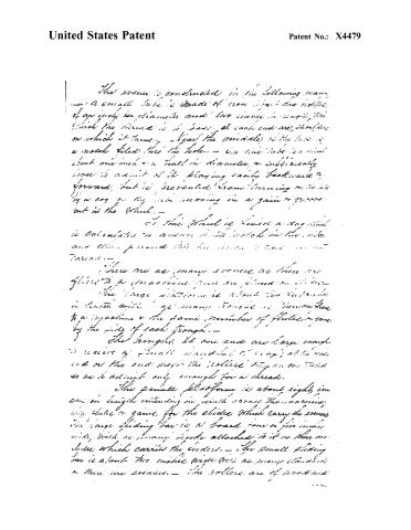
The even is constructed in the following manner: a small tube is made of iron about two eighths of an inch in diameter and two inches in length, into which the thread is to pass at each end are shoulders on which it turns. Near the middle of the tube is a notch filed into the hole. The tube is about one inch and a half in diameter and sufficiently loose to admit of its playing easily backward and forward, but is prevented from turning or moving by a cog on the tube moving in a gear or groove cut in the wheel.
To the wheel is fixed a rod which is calculated to answer to the notch in the tube and when pressed into the same it acts as a thrust.
There are as many screws as there are slides to a machine and are placed on either side. The large platform is about the width in length and at many times is furnished to a machine and the same number of slides are by the side of each trough.
The screws at one end are large enough to receive a small spindle to carry, at the other end or the end near the roller, they are controlled so as to admit only enough for a thread.
The small platform is about eight inches in length extending in width across the machine, into which a guide for the slides which carry the screws. The large sliding bar is a board, one or two inches wide, with as many hooks attached to it as there are slides which carries the leaders. The small sliding bar is about the same width with as many standards as there are screws. The rollers are of wood and
Page 4.
United States Patent
Patent No.: X4479
about two inches in diameter, covered with fine
cyclic substance and pressed together by clamps.
The large slides are of wood about one foot three
inches in length and fitted to the flutes again
of the large platform. The small slides are
about five inches in length fitted to the flutes
again of small platform.
The main arbor is placed on the
middle joist near the upper face, the large wheel
being on the back side of the frame; two or
three of the large wheels are a number to move.
The small arbor is placed on the
same joist near the foot of each. It has a
small wheel as a number of grooves of different
heights is carried by a hand from the top
of the large wheel; the crank of the main
arbor is grooved by a man, carrying the large
wheel away, which grooves horizontally into
invisibility under the large wheel, and
in order of the bar sliding up then the
platform is raised out by that for some more
invisibility together with the loaded quantity
backward & forward.
The intermediate cylinder or drum
is placed just above the lower cross bar at the
right hand of the frame and turned by a hand
from the large wheel. The large platform is
on the top of the frame at the left hand from the
wheel. The top of the right hand and a
small platform is between the large platform and
wheel.
The final cylinder or drum is placed
on the right hand directly under the wheel and
Page 5.
United States Patent
Patent No.: X4479
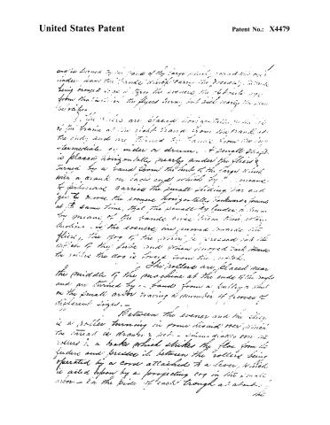
and is driven by the hand of the large pinion, round the axis under hand the handle which carries the gear, a handle being arranged to act as lever to operate the oblique edge from the motion of the flywheel turning, but with nearly the same direction.
The rollers are placed horizontally on the side of the frame at the right hand from the crank, at the end, and are turned by hands from the intermediate or under or drum. A small shaft is placed horizontally nearly under the flies, turned by a hand from the hand of the large wheel, with a crank on each end which by means of pinion carries the small pinion bar and gives more the crease horizontally backwards, forward at the same time, that the small fly under a beam by means of the handle gives them their motion. The creases are moved towards the flies, the dog of the pinion is pressed into the notch of the blade and then moved back towards the roller the dog is forced from the notch.
The rollers are placed near the middle of the machine at the ends of the table and are turned by hands from a handle a wheel on the small and having a number of grooves of different sizes.
Between the creaser and the flies is a roller turning in some kind of way when the thread is drawn & etc. — immediately over the rollers is a brake which strikes the flies from the feeder and presses it between the rollers being operated by a cord attached to a lever which is acted upon by a projecting cog in the small wheel — in the side of each trough as above.
Page 6.
United States Patent
Patent No.: X4479
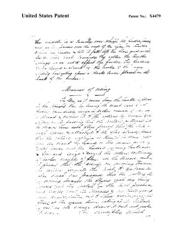
The middle is a tumble over which the feeder passes, and as it passes over the end of the flap the tumble drives the feeder to let it fall into the slot and as the feeder goes back towards the roller the tumble swings so as not to effect the feeder. The feeder is so closed or closed by the hook of the large sliding bar acting upon a block lever placed on the back of the feeder.
Manner of using
The flap as it comes from the handle is placed in the trough. Then by turning the crank each time the feeder immediately brings a broken shank of wire so a thread is carried it to the rollers by means of the slider, so it having first the roller a thread is drawn from each roller placed into the hole in each eyelet, so attached to the flap already known has the rollers, nothing is thought to come out from the crank the thread is two pieces as in a plate comes and the feeders opening back and forward keeps & carries the rollers, continuing a broken shank of flap to the thread, and a passed through the eyelet on moving forward the motion carries the back to the back the flap which has passed into the roller, so moving towards the flyers each dog being forced into the pocket in the back, pressed on and until the threads & shanks pass and remain there until their outer edge is there at the same time taking up the thread as the cranks draw it out and make it even. The principles which
Page 7.
United States Patent
Patent No.: X4479
we particularly claim in the described machine
are those embraced in the rollers, the leader and
the covers.
Hartford, New York, May 20th, 1876
Witnesses:
J. H. Jones
J. T. Brown
J. W. Smith
*Filed & recorded anew Feb 25th, 1875.
Page 8.
United States Patent
Patent No.: X4479
DRAFTSMAN'S DIVISION.
All communications should be addressed to
"The Commissioner of Patents"
Washington, D. C.
DEPARTMENT OF THE INTERIOR,
United States Patent Office,
Washington, D. C.
SIR:
The printed copies of Patent No. 189 are exhausted.
As soon as printed a copy will be mailed you to complete your order.
By direction of the Commissioner:
Very respectfully,
Chief Clerk.
814016-97-5m
Published accounts: journal notice
Notice in the monthly list of patents
Franklin Journal and American Mechanics' Magazine, vol. 2 (1826), p. 254 · View the page
In the machine for spinning flax and hemp, June 22, W. Hunt and W. Hoskins, New York.
About this record
- Patentee
- DATAMP
- Date
- the Name and Date index of patents, DATAMP, USPTO records
- Invention
- DATAMP
- Listed in
- the Name and Date index of patents, DATAMP, USPTO records, Jim Shaw's X-patent list, the Journal of the Franklin Institute, S. A. Elliot's printed list of patents, Burke's List of Patents (1847)
- S. A. Elliot's printed list of patents gives the same name and date.
- Burke's 1847 Patent Office list gives the same patent.