

Drawings and documents
National Archives restored drawings: drawing
John M'Clintic's Patent Drawing for a Machine for Mortising and Tenoning Timber

National Archives, Restored Patent Drawings (Record Group 241) · Full-size scan at the National Archives · Catalog record
Show the text on the drawing Hide (195 words)
Words on the drawing as machine-read by the National Archives; not checked. Useful mainly for searching.
seccess / 143. WOOD WORKING. / 2. GENERAL WORK MACHINES. / [173] Mortising. / #150 / 4896.7 / John Milelinle is / fronting / Marchine for mortising and tenoning timber. / Oct 1827. / Fig / Fig 2. / Fig3. / Fig4: / References / References / Fig 1 / Permanent guide / Perspective views / Moveable ditho / ferew for adjusting the moveable guide. / Chisel for sinking tenores for venetian blinds / Is / sliding frame to secure the timber be / A Ferame dille for 0-5- mortising bench. window sashes, No. / mortised, in its proper place, and prevent / to / and chise is drawn out / B. studs / D Toprail upright connecting or posts. the / c. upright pasts. / right secure the above frame. / throug. h the groones in the when / chisel frame which slided up Idown in grooved / F3. Rail with eye bolts connecting it ehivel / N. oren spaces in the tive spright studs, through / 11' Tron straps connecting lever and / frame pin and nuts / are flash at the bottom groove in the / which the timber to be montized, for apos, which / Ex. byzin out from its proper / moveable table. / Mortising chisel. / to show it more distinctly. / P. The lever. / H. Fail pin for forcing the table in, or out
USPTO scan
The patent as scanned by the USPTO
-
 Page 1
-
 Page 2
-
 Page 3
-
 Page 4
-
 Page 5
-
 Page 6
-
 Page 7
-
 Page 8
-
 Page 9
-
 Page 10


U.S. Patent and Trademark Office · Google Patents
Show the transcription Hide (4,133 words)
Machine transcription (LightOnOCR) of the pages as scanned by the USPTO, most of them the handwritten copies made when the records were restored after the 1836 fire. Not checked; it can misread handwriting, so compare it with the scan.
Page 1.
4896X
J. Mc Clintic,
Mortising Machine.
Patented Oct. 8, 1827.
Fig. 2
Fig. 3 Fig. 4
Fig. 1
A.M. PHOTO-LITHO. CO. N.Y. (OSBORNE'S PROCESS)
Page 2.
John McClintic
Letters Patent Patented Oct. 8th 1827.
Refused Aug. 27, 1835
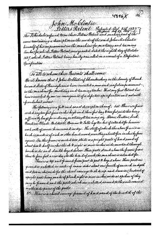
The Schedule referred to in these Letters Patent and making part of the same containing a description in the words of the said John McClintic himself of his improvement in the machine for mortising and tenoning timber, for which Letters Patent were granted dated the eighth day of October 1827, which Letters Patent being hereby cancelled on account of a Defective Specification.
To all to whom these Presents shall come
Be it known that I John McClintic of Chambersburg in the County of Franklin and State of Pennsylvania have invented a new and useful improvement in the machine for mortising and tenoning timber. That my first Patent has been cancelled by me in consequence of a defective specification and not with fraudulent intent.
The following is a full and exact description thereof: 1st—There is a frame erected say two feet four inches high and three feet long & two feet wide this being sufficiently large for ordinary mortising & tenoning viz. Doors, Shutters, Sash, Venetian Blinds, Bedsteads, Bureau & Table legs &c. but if intended for heavier work will of course be increased in size. The stuff of which the above frame or huck is made is of oak or other hard wood, scantling about five inches by four square. On this frame is erected two studs or upright posts of hard wood of about two & half inches thick & eight or nine inches wide mortised through bench sides and double keyed below. These posts stand above the frame from three to four feet according to the kind of work the machine is intended for.
There is a top rail framed from post to post & keyed above. These posts are grooved or rabbitted in centre of inner sides about one fourth of an inch in depth and two inches wide for the chisel carriage to slide up and down in (Instead of upright posts being made of plank eight or nine inches wide as spoken of they may be framed, and the parts which are rabbitted, screwed to the rails connecting the side pieces of the posts)
2d—There is a chisel carriage framed of hard wood of the breadth of the
Page 3.
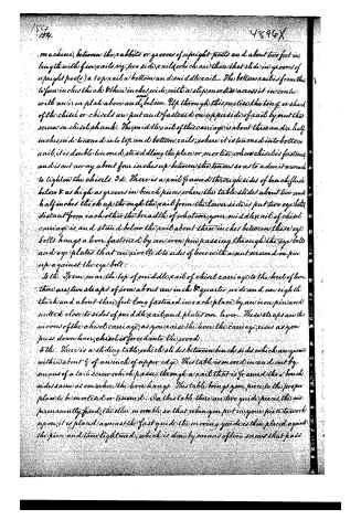
machine, between the rabbets or grooves of upright posts and about two feet in length with five rails, viz. two side rails (which are those that slide in grooves of upright posts) a top rail, a bottom and middle rail. The bottom rail is from three to four inches thick & three inches wide, with a slip mortise across it in centre with an iron plate above and below. Up through this mortise the long or shank of the chisel or chisels are put and fastened on upper side of rail by nut that screws on chisel shank. The middle rail of this carriage is about three and a half inches wide tenoned into top and bottom rails; where it is tenoned into bottom rail, it is double tenoned, straddling the place or mortise where chisels fastened, and is cut away about four inches up between the tenons so as to admit it around to tighten the chisels. 3d. There is a rail framed through sides of bench flush below & as high as grooves in bench piece where the table slides about two and half inches thick up through the rail from the lower side is put two eyebolts distant from each other the breadth of whatever your middle rail of chisel carriage is, and stand below the rail about three inches between these eyebolts hangs a lever fastened by an iron pin passing through the eyebolts and eye plates that are rivetted to sides of lever with a nut screwed on pin up against the eyebolt.
4th. From near the top of middle rail of chisel carriage to the heel of lever there are two straps of iron about an inch & quarter wide and an eighth thick and about three feet long fastened in each place by an iron pin and nutted close to sides of middle rail and plates on lever. These straps are the movers of the chisel carriage, as you raise the lever the carriage rises as you press down lever, chisel is forced into the wood.
5th. There is a sliding table which slides between bench sides which are grooved within about ½ of an inch of upper edge. This table is moved in and out by means of a tail screw which passes through a rail that is framed thru bench sides same as over where the lever hangs. This table brings your piece to the proper place to be mortised or tenoned. On this table there are two guide pieces, the one permanently fixed, the other movable, so that when you put in your piece to work upon, it is placed against the fast guide, the moving guide is then placed against the piece and then tightened, which is done by means of two screws that pass
Page 4.
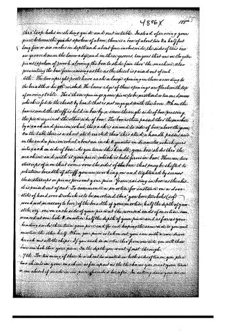
thru' loop holes in sliding guide and put in table. Instead of moving your piece between the guides spoken of above, there is a box of about two & a half feet long five or six inches in depth and about four inches wide, the sides of this box are grooved near the lower edge, and in those grooves, tongues that are on the guide pieces (spoken of) work allowing the box to slide fair thru' the machine, also preventing the box from raising as the as the chisel is raised out of cut.
6th. The two upright posts have each a large opening in them according to the breadth or height wished. The lower edges of these openings are flush with top of moving table. Thru' those openings your piece to be mortised or tenoned moves which is fed to the chisel by hand that is not engaged with the lever. When the box is used the stuff is held in box by a screw through side of box pressing the piece against the other side of box. The box is then passed thru' the machine by a rack and pinion wheel, the rack is screwed to side of box above the groove on the table thru' is a short stud erected thru' this stud, a handle passes and on the end a pinion wheel about an inch & quarter in diameter which goes into rack on side of box. As you turn this handle, your box slides thru' the machine and with it your piece, which is held firm in box. There are two stirrups of iron that come over the sides of the box that may be shifted to whatever breadth of stuff you are working on and tightened by screws these stirrups or pieces prevent your piece from raising in box as the chisel is raised out of cut. To commence a mortise for instance on a door stile of hard wood which is to be mortised thru', you bore two holes (soft wood not necessary to bore) of the breadth of your mortise, half the depth of your stile, viz. one on each side of your piece at the reversed ends of mortise commenced at one hole & mortise half the depth of your piece and as far as your heading scribe then turn your piece end for end keeping the same side to you and mortise the other half. When your piece is taken out, you can with a core driver knock out all the chips. If you wish to mortise thru' from one side you will then bore one hole thru' your piece on the depth you want if not through.
7th. For tenoning, if there be a shoulder wanted on both sides of tenon, you place two chisels in your machine as far apart as the thickness you want your tenon or one chisel if made in one piece described hereafter. In cutting down your tenon
Page 5.
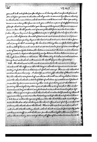
you will take out of about one fourth of an inch, leaving about one fourth of an inch stand before you come to shoulder, which quarter is removed by a former chisel of tenons or moulings thro' from one side you will have a piece of stuff filled to inside of box for chisel to cut against, that your box may not be injured, this piece is screwed down in box; For the greater ease of moving the stile from mortise to mortise (where they are long and heavy) there is a piece of stuff about half inch or three quarters thick fitted to breadth of box inside and screwed down in it (screws countersunk projecting beyond the box at each end) some two or three feet or what may be thought necessary. For bevel mortising there is a false bottom fitted to breadth of box inside rounded at one end and a pin of iron run through sides of box, and false bottom, this bottom is raised at the loose end to whatever play wanted is kept at that pitch by wedge between the two bottoms or screw up through lower bottom or otherwise. This bottom may be taken out when not mortising bevel work which will increase the depth of your box if wanted.
8th. The chisels used in this machine are similar to the common mortising chisels with the difference that the longs or shanks are square and a saw cut on tang to fasten them in bottom part of chisel carriage. There are also other chisels used in the machine, viz. A chisel for mortising for the stiles of Venetian shutters, this chisel is composed of a socket made with an oblong hole in it to receive the chisel, which is two half bits of whatever size wanted and fastened in socket by two screws running thro' side of socket against the bits and pressing them tight together against the other side of socket. This socket has a round tang so that it may be turned in machine to suit right or left stiles. Also a square or four sided chisel which is intended for rails, viz. the usual square mortising cross muntions & meeting rails; for this kind of chisel there is a hole bored within the square of the mortise the chisel then cuts down the four sides the block or chip sticking in the chisel is forced out of at by a crooked tool entering the chisel above the block. There is also used in machine what I call double & treble cutting chisels; which chisels are used (principally) when working on stuff in which the core packs rather tight. Also used at times when the mortising does not go through. One of these chisels is similar to the
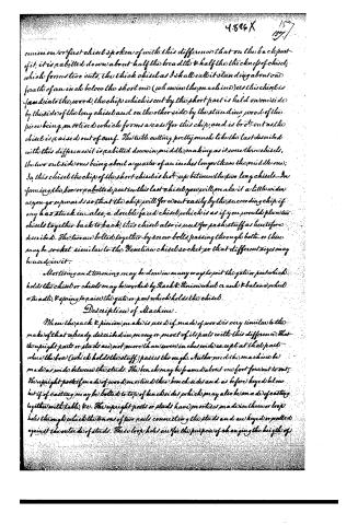
Page 6.
common or first chisel spoken of with this difference that on the back part of it, it is rabbited down about half the breadth & half the thickness of chisel, which forms two cuts, the thick chisel as I shall call it standing about one fourth of an inch below the short one (when in the machine) as this chisel is fast into the wood, the chip which is cut by the short part is held on one side by the side of the long chisel and on the other side by the standing wood of the piece being mortised which forms a case for this chip, and is brot out as the chisel is raised out of cut. The little cutting pretty much like the last described with this difference it is rabbited down in middle making as it were three chisels, the two outside ones being about a quarter of an inch longer than the middle one; In this chisel the chip of the short chisel is brot up between the two long chisels. In forming the box or rabbited part in this last chisel you will make it a little wider as you go upwards so that the chip will for ever easily by the succeeding chip if any has stuck in also, a double faced chisel which is as if you would place two chisels together back to back, this chisel also is used for push stuff as heretofore described. The two are bolted together by screw bolts passing through both or there may be socket similar to the Venetian chisel socket so that different sizes may be used in it.
Mortising and tenoning may be done in many ways to join the gate or part which holds the chisel or chisels may be worked by Rack & Pinion wheel or axle & balance wheel or tackle, & spring to raise the gate or part which holds the chisel.
Description of Machine.
When the rack & pinion make is used if made of wood is very similar to the make of that already described in many or most of its parts with this difference that the upright parts or studs are not more than seven inches wide except at that part where the box (which holds the stuff) passes through. Neither need the machine be made as wide between the studs. The bench may be framed about one foot from out to out, the upright parts if made of wood mortised into bench sides and as before keyed below but if of casting may be bolted to top of bench sides which may also be made of casting together with table, &c. The upright parts or studs have mortises made in them or loop holes through which the tenons of two rails connecting the studs and are keyed or nailed against the outside of studs. These loop holes are for the purpose of changing the height of
Page 7.
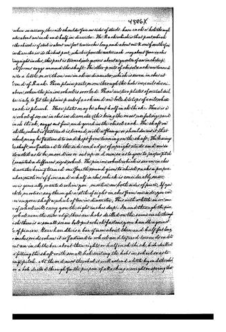
4896X
when necessary, the rails should be fair on sides of studs—have each a hole through which about an inch and half in diameter. The Rack which is that part which the chisel is of steel is about one foot ten inches long and about one & one fourth of an inch in diameter in its thickest part, which is from the centre each way about four inches long eight inches; this part is turned into grooves about a quarter of an inch deep, which forms cogs around the shaft. The other parts of chisel rack are turned into a little more than an inch in diameter, which is seven inches at the end of Rack. These plain parts move through the holes in rails described above, when the pinion wheel is worked. There are two plates of metal drilled precisely to fit the plain parts of rack and are bolted to tops of rails when rack is plumb. These plates may be about half inch thick. There is a wheel of seven inches in diameter (this being the most useful size) and one inch thick, cogs cut fine, and geared in the chisel rack. The shaft on which the wheel is fastened is turned with a flange or shoulder on it that wheel may be fastened to and kept from turning on the shaft. The bearing in shaft, are fastened to the sides and edges of upright studs, and are so constructed as to be moved in or out up or down, so as to gear to proper pitch (pointed a different sized wheel). The pinion wheel which is seven inches in diameter being turned one fourth round gives to chisel rack a perpendicular motion of five and a half inches, which is considerably more than is generally pointed when you mortise on both sides of piece. If you wish to mortise say through a stile of eight inches from one side, you can see on your shaft a wheel of ten in diameter. This with a little more motion of wheel will carry you the eight inches deep. In and through the pinion wheel near the outer edge, there are holes drilled on the same circle through which there is a small screw bolt put which fastens your handle against the pinion. Your handle is a bar of iron about three and half feet long, six inches wide when it is fastened to wheel and tapered towards its end into an inch the bar about three eights or half inch thick, hole drilled so filling the shaft with small holes cutting the holes in wheel so as to run up pitch. At the end near the wheel it will extend a little beyond the wheel, and a hole drilled through for the purpose of attaching a weight or spring that
Page 8.
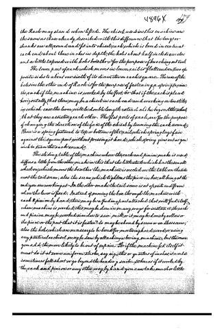
the Rack may stand when lifted. The chisel used in this machine are the same as those already described with this difference that the long or shanks are all round and fit into chisel rack which is bored in concentric rack end about three inches in depth, the holes about half inch diameter and a little tapered with holes bored through for the purpose of knocking out tool.
The lower part of each which moves in lower rail is flattened on two opposite sides to about one sixth of its diameter on each square. The use of the holes in the other end of Rack is for the purpose of fastening a spring to raise the rack if the machine is worked by the foot, or that if the rack is placed horizontally that there may be a chisel in each end and working on two sides, in which case the lever will be double length extend alike beyond the wheel, that they are assisting each other. The flat parts of rack are for the purpose of changing the direction of the face of the chisel by turning the rack round; There is a spring fastened to top or bottom of the rail, which spring lays fair against the square part without pressing it hard; which spring gives out as you wish to turn the rack round.
The sliding table of the machine where the rack and pinion make is used, differs a little from the other make in this that the little stud which has the small wheel on which moves the box this the machine is erected on the table on the side next the tail screw; also the screw which tightens the piece in box, all being at the end you are working at. In the other make the tail screw is at opposite end from where the lever is fixed; Instead of moving the box through the machine with rack & pinion by hand, there may be a feeding part attached that will feed itself when machine is worked; this may be done in many ways for instance, the rack and pinion may be worked similar to saw mill, or it may be done by rollers or the piece or the part that it is fastened to may be shoved by screw or endless screw; also the holes which are necessary to be bored for mortising hard wood, or using any particular chisel may be done by attaching a boring machine; but the more you add, the more likely to be out of repair. For if the machine fed itself it must do it at some uniform stroke, say e.g. this or quarters of inches, it would sometimes fall short or go beyond the heading scrib, whereas if it worked by the rack and pinion or any other way by hand, you can take much or little
Page 9.
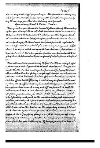
d, according to the stuff you working on. The aforesaid machinery may be worked by water, steam, horse, hand, or any other power, that may answer by using the necessary gear. That described being used by hand.
Operation of Rack & Pinion Machine.
When you place your piece in the box, and tighten it there by the screw through the box, your sliding table on which the box rests, is moved in or out, bringing the piece in box to the proper place to be acted on; you then let your chisel, which is in the rack rest on top of piece; give your lever what ever inclination you choose by changing the thumb screw pin (which passes through wheel & rack) into a different hole on wheel higher or lower as you may want it. If the stroke is to be deep, it will be best to set the lever about one eighth of the circle to wheel above level. This, when you have pressed your lever or handle to one fourth of the circle below level, will give one fourth of wheel or five and half inches deep.
Where the machine is operated on by the foot, it will be necessary to affix a rattle connected with the part which holds the chisel or with the upper lever handle; Further it will be necessary where foot is used for forcing the chisel, the proof that there be a spring or weight sufficiently strong, or heavy to raise gate or part which holds the chisel out of the cut, when the pressure of the foot is taken off the handle. If spring is used it may be of wood, steel, or iron anything else of sufficient strength and elasticity, and may be attached to frame of machine, in such a way as to lift the part which holds the chisel. In the rack & pinion machine the spring may be a spiral spring made of strong wire, and may be attached to top of chisel rack or set below wheel operating on the rack, in this case the wheel is pulled downward in such a way that the rack is forced upwards, besides spring there may be a weight attached to wheel or to the end of handle next to wheel which weight (little heavier than the chisel rack, this weight being necessary to balance the rack, that it may stand in any position where the hand is used instead of foot. Instead of applying springs or weight for the purpose of raising the tool out of cut or cut, they may be applied so as to force it into cut as many ways, one of which may be in this way. By hanging a weight to lever as far
Page 10.
9
4896X 161
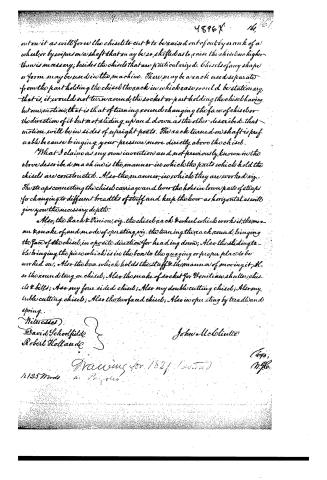
out on it as will force the chisel to cut & to be raised out of cut by crank of a wheel, or by wiper on a shaft that may be so shifted as to raise the chisel no higher than is necessary; besides the chisel that are particularized. Chisels of any shape or form may be used in the machine. There may be a rack used separate from the part holding the chisel the rack in which case would be stationary, that is, it would not turn around, the socket or part holding the chisel having but one motion, that is that of turning round changing the face of chisel or the direction of it but not sliding up and down as the other described. that motion will be in sides of upright posts. The rack turned on shaft is preferable because bringing your pressure more directly above the chisel.
What I claim as my own invention and not previously known in the above described machine is the manner in which the parts which hold the chisel are constructed. Also the manner, in which they are worked viz. The straps connecting the chisel carriage and lever the holes in lower parts of straps for changing to different breadths of stuff and keep the lever as horizontal as will give you the necessary depth.
Also, the Rack & Pinion, viz. the chisel rack & wheel which works it, the manner & make of, and mode of operating, viz. the turning the rack round, bringing the face of the chisel, in opposite direction for heading down; Also the sliding table bringing the piece which is in the box to the guaging or proper place to be worked on, Also the box which holds the stuff & the manner of moving it; Also the round tong on chisel; Also the make of socket for Venetian shutter, chisels & bills; Also my four sided chisel; Also my double cutting chisel; Also my triple cutting chisel; Also the two faced chisel; Also in operating by treadle and spring.
Witnesses
David Schoolfield
Robert Hollande
John McClintic
Drawing for 1821 (dated)
1125 Words
1670, M.96.
Published accounts: specification
Specification printed in the Mirror of the Patent Office (1828) with its plate


American Journal of Improvements in the Useful Arts, and Mirror of the Patent Office, vol. 1 (1828), printed p. 47 · View the page
Show the transcription Hide (1,592 words)
Text of the specification as printed in the Mirror of the Patent Office, machine-transcribed from the page scans (GLM-OCR); not proofread. Check the scan for figures and reference letters.
MACHINE FOR MORTISING AND TENONING TIMBER,
By John M'Clintic, of Chambersburg, Pennsylvania.—(See Plate, 3.)
Specification. — There is a frame erected, say two feet four inches high, and three feet long, and two feet wide, (this being sufficiently large for ordinary mortising and tenoning, viz. doors, sashes, Venetian blinds, shutters, bedsteads, bureaus, tables, &c.) but if intended for heavier or larger work, will of course, be increased in size.
The stuff of which the above frame or bench is made, is oak scantling of about five inches by four square. On this frame is erected two studs or upright posts of oak, or other hard wood, of about two and a half inches thick, and eight or nine inches wide, mortised through the bench sides and double keyed below. These posts, stand above the frame, from three to four feet, according to the kind of work the machine is to be employed for.
There is a top rail framed from post to post and keyed above; these upright posts are grooved, or rabitted in the centre, on the inner sides, about one fourth of an inch in depth and two inches wide.
2. There is a chisel carriage framed of hard wood, of the breadth of the machine, between the rabbits or grooves of upright posts, and about two feet in length, with five rails, viz. two side rails, which are those that slide in the grooves of upright posts; a top rail, a bottom and middle rail, the bottom rail is of, from three to four inches thick, and three inches wide, with a slip mortise across it in the centre, with an iron plate below; up through this mortise the tang of the chisel, or chisels are put, and fastened on the upper side of the rail by a nut that screws on the tang of the chisel. The middle rail of this carriage is about three and a half inches wide, tenoned into the top and bottom rails; where it is tenoned into the bottom rail, it is double tenoned, straddling the place in the bottom rail, where the chisels are fastened; also, cut away about four inches up, so as to admit a wrench to tighten the chisels.
3. There is a rail framed through the sides of the bench, flush below. — Through this rail, from the lower side is put up two eye bolts, distant from each other the breadth of whatever your middle rail of chisel carriage is, standing below the rail about three inches,—between these eye bolts, hangs the lever, fastened by an iron pin, passing through the eye bolts and eye plates that are rivetted on sides of lever.
4. From the top of the middle rail of chisel carriage to the heel of the lever, there are two straps of iron, about an inch and a quarter wide and an eighth of an inch thick, fastened in each place by an iron pin, and nutted close to the sides of middle rail, and sides of lever; these straps are the movers of the chisel carriage. As you raise the lever, your chisel rises, as you draw down your lever, the chisel is forced into the wood.
5. There is a sliding table which moves between the sides of the bench. This table is moved in and out by means of a tail screw, which passes through a rail that is framed through the sides of bench, similar to the one where the lever hangs; this table brings your piece into the proper place, to be mortised or tenoned. On this table there are two guides, the one permanent, the other moveable, so that where you put in your piece to work upon, you move the sliding guide up against the piece, and there tighten it, which is done by means of two screws that pass through loops in the slide, and nut in the table. There is also a sliding frame, which slides up and down, between the two upright posts; this frame is fastened by two screws, one on each side passing through the upright post into the frame, and when this frame is put down on the piece to be mortised or tenoned, it is there tightened, to prevent the piece from raising as the chisel or chisels act.
6. The two upright posts have each a large mortise made in them, according to the breadth or height wished for. The lower edges of these mortises or holes are flush with the moving table; through those holes your piece to be mortised or tenoned moves, which is fed to the chisel, by the hand that is not engaged with the lever—there are also two moving guides attached to the frame, that move up and down, which are used when you are working upon any thing very thin, to prevent it from twisting about. To commence a mortise, for instance, on a door stile or sash, which is to be mortised through, you bore two holes of the breadth of your mortise, half the depth of your stile, viz. one on each side of your piece, at the reversed ends of your mortise—commence at one hole and mortise half the depth of your piece, and as far as your scribe, then turn your piece end for end, keeping the same side to you, and mortize the other half. When your piece is taken out you can, with a core driver, knock out all the chips.
7. For tenoning, if there be a shoulder wanting on both sides of the tenon, you insert two chisels, as far apart as the thickness you want your tenon; cut down half the breadth of the tenon, then turn your piece and cut the other half, leaving something like a quarter of an inch, before you come to the shoulder stand; the shoulder being sawed down, this quarter of an inch is removed by a finer chisel by hand.
8. The chisels belonging to this machine, are similar to the mortising chisel, with this difference, there the tangs are square and a screw cut on them for the purpose of fastening to the rail of the chisel carriage. There are also two other chisels belong-ing to the machine, viz. a chisel for mortising for the slats of Venetian blinds. This chisel has a round tang, so that it may be turned into the machine, so as to suit right and left stiles. Also a square or four sided.chisel, which is intended for sash, viz. the small square mortising, cross muntens and meeting rails—there This is a page from: book about US patent office including patent specifications from 1828.
Transcribe all text exactly as it appears in the image. Preserve line breaks if necessary and include any numbers or labels in the margins. Mark illegible words with [?].
Fig. 1.
Fig. 3.
Fig. 4.
Fig. 2.
Drawn by U. Brown
Original from NEW YORK PUBLIC LIBRARY may be added to the machine, chisels of any shape whatever.
Mortising and tenoning may be done in many ways, viz. the gate or part which holds the chisels may be worked by rack and pinion, cranks and balance wheel, or treadle, and spring to raise the gate.—The piece to be mortised or tenoned is moved on the chisel by hand, but there may be a feeding part put to it in many ways: for instance, there may be a rack and pinion which will move the piece similar to a saw-mill; or it may be done by rollers, or it may be shoved by screw, or endless screw. Also, the holes which are necessary to be bored for mortising, which are bored by hand for this machine, may be done by attaching a boring machine that may be worked by a wheel or simple crank, as it were, on the head of a brace; but all this additional work is better to be dispensed with, as it will render a machine more complicated, and more liable to be out of repair, and upon the whole, very little or no expedition gained.
JOHN M'CLINTIC
WM. ELLIOTT,
R. W. FENWICK.
Witnesses.
REFERENCES.—PLATE III.
A Fig. 1 and 2. Frame or bench.
B Fig. 1 and 2. 2 Upright studs or posts.
C Fig. 1 and 2. Top rail connecting the upright posts.
D Fig. 1 and 2. Chisel frame which slides up and down in grooves.
E Fig. 1 and 2. Rail with the eye-bolts connecting it with the lever.
F Fig. 1 and 2. Two iron straps connecting the lever and chisel frame by pins and nuts.
G Fig. 2. Sliding table, drawn out from its proper place, to show it more distinctly.
H Fig. 2. Tail pin for forcing the table in, or out.
I Fig. 2. Permanent guide.
J Fig. 2. Moveable guide.
K Fig. 2. Screws for adjusting the moveable guide.
L Fig. 1 and 2. Sliding frame to secure the timber to be mortised, in its proper place, and to prevent it from rising as the chisel is drawn out.
M Fig. 1 and 2. Screws passing through the grooves in the upright studs, to cure the above frame.
N Fig. 1 and 2. Open spaces in the two upright studs, through which the timber to be mortised, passes, which are flush at the bottom with the groove in the moveable table.
O Fig. 1 Mortising chisel.
P Fig. 1 and 2. The lever.
Fig. 3 Chiseler for sinking tenons for Venetian blinds.
Fig. 4 Chiseler for mortising window sashes, &c.
Published accounts: journal notice
Notice in the monthly list of patents
Journal of the Franklin Institute, vol. 5 (1828), p. 211 · View the page
In the machine for mortising and tenoning timber; John M-Clintic, of Chambersburg, Pennsylvania, Oct. 8.
Published accounts: journal notice
Notice in the monthly list of patents
Journal of the Franklin Institute, new ser., vol. 6 (1830), p. 18 · View the page
The above named machine is very clearly described, and very perfectly represented in the drawing; in its general structure it resembles a machine patented by Mr. John M'Clintic, Chambersburg, Pennsylvania, October 8th, 1827.
About this record
- Patentee
- the Journal of the Franklin Institute, Journal
- Date
- the Name and Date index of patents, USPTO records, Jim Shaw's X-patent list
- Invention
- the Name and Date index of patents
- Listed in
- the Name and Date index of patents, USPTO records, Jim Shaw's X-patent list, the Journal of the Franklin Institute, the Mirror of the Patent Office (1828), S. A. Elliot's printed list of patents, Burke's List of Patents (1847)
- A drawing was printed in the Mirror of the Patent Office (1828).
- The patentee's full name comes from the Franklin Institute's journal.
- The specification was printed in the Mirror of the Patent Office (1828).
- The Mirror of the Patent Office's supplementary list gives the same patent.
- S. A. Elliot's printed list of patents gives the same name and date.
- Burke's 1847 Patent Office list gives the same patent.