

Drawings and documents
Published accounts: specification
Specification printed in the Mirror of the Patent Office (1828) with its plate
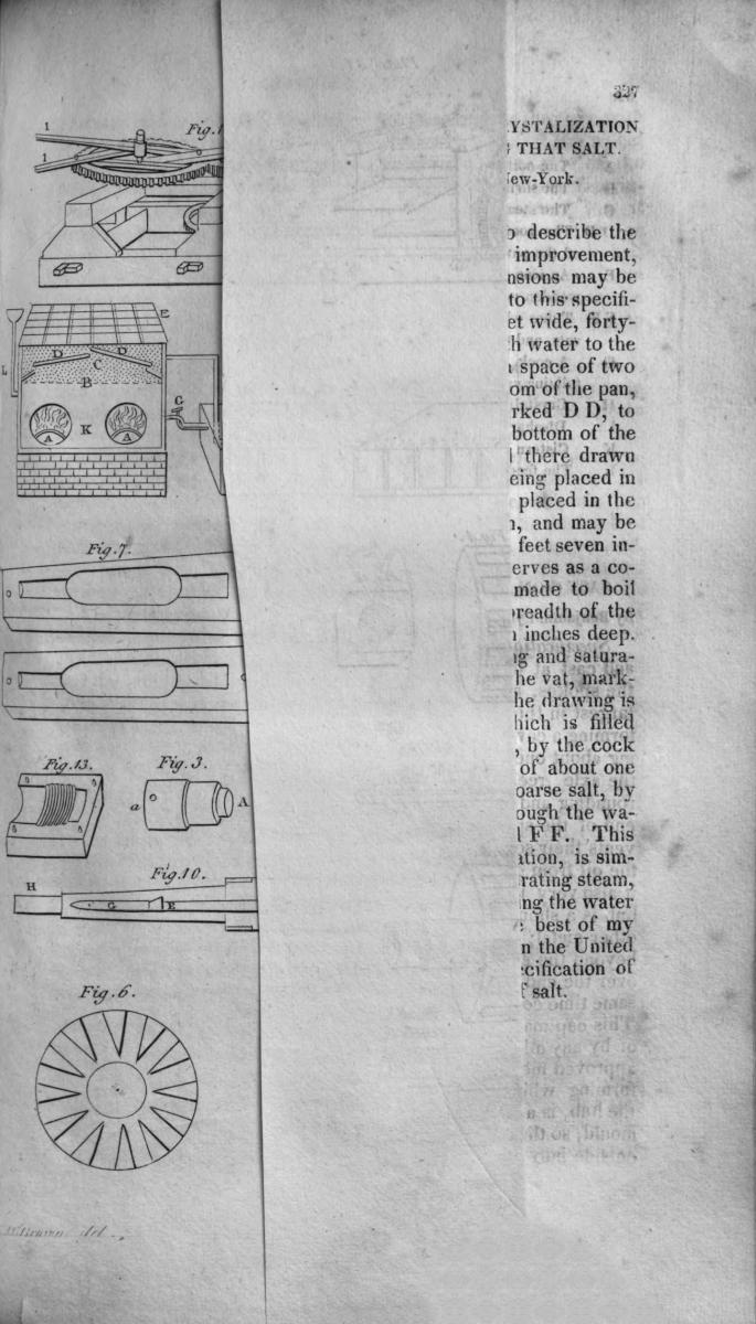
American Journal of Improvements in the Useful Arts, and Mirror of the Patent Office, vol. 1 (1828), printed p. 328 · View the page
Show the transcription Hide (1,055 words)
Text of the specification as printed in the Mirror of the Patent Office, machine-transcribed from the page scans (GLM-OCR); not proofread. Check the scan for figures and reference letters.
CAST IRON, OR OTHER METAL HUBS, FOR WHEEL CARRIAGES
By Benjamin Lymans, of Manchester, Connecticut — See plate XXXI, fig. 3 to 14.
Specification. — This hub is made of cast iron, or other metal, and cast at one casting, whole and entire, with the mortises for the spokes, a bore or hollow through the hub for the axle tree, largest in the middle, for about one half of the length of the hub, forming a cavity or chamber for containing oil or grease, and leaving about one quarter of the length at each end to run close upon the axle tree, as a substitute for boxes; and a rim of iron surrounding and forming this cavity for oil, and between that and the end of the spokes, and on which they firmly rest; which prevents their settling or working loose in the mortises, and prevents the oil from getting to the spokes, to cause them to work loose; it also very materially strengthens the hub. On each end of the hub is a shoulder cast, for receiving a band of wrought iron, or other metal; these strengthen and ornament the hub; they project beyond the end of the hub, and the outer one is formed into a cap over the end of the axle tree, keeping out the dirt, and at the same time confining the oil or grease within the cavity and boxes. This cap may be secured to thehub by driving it on when hot, or by any other means, as may be thought best. But the most approved method is, to put it on with a screw; the method of forming which is hereinafter described. Through the body of the hub, is a hole formed by placing a tube of tin or metal in the mould, so that when thehubis cast, thetube will pass from the outside intothe cavity; through this the oilor grease is conveyed to the axle tree, and confined there by stopping the tube with a cork or screw. This saves the trouble of taking off the wheel to grease it. This tube may be placed on either side of the spokes. This hub may be made of any size to suit any description of carriages; for a one horse wagon, it is sufficient that it be cast eight and a half inches in length, with a bore to receive an iron axle tree of one inch diameter at the small end, one and a half inches at the other end of the hub; leaving the thickness of the hub at the small end about half an inch, with an almost square rise in the middle, to a diameter of about six inches, sufficient to give the length and depth of the mortise.
The pattern which forms the mould for casting this hub is made in three separate parts, so that when put together they form the shape of the hub. The back part of the body of the pattern is separate from the middle part at the commencement of the rise containing the mortises for the spokes. The outer part separates from the middle part at the front end of the mortises for the spokes, so as to leave the strans or bars between the mortises and the rim in the centre attached to the rising part at the back of the mortises, that it may be moulded and drawn from the sand, leaving the sand whole which forms the mortises. On each end of the pattern is a centre turned of the size of the axle tree, for the purpose of making a print in the mould for setting in the core of sand which forms the bore of the hub. These three parts are moulded in three separate flasks. The core of sand which forms the box for the axle and cavity, is formed in a mould consisting of two pieces of wood or metal, one half the mould being cut in each and put together. To cast a screw upon the small end of the hub for receiving the cap, an iron or other metal nut, with a female screw cut in it, is so placed in the mould as to form that part of the hub. When these three parts of the hub are moulded, the several flasks are put together, the core set in, and a fourth flask put on the back end, for the purpose of regulating and securing the core. The pattern for moulding the cap, containing the female screw, is made of two pieces of wood, or metal, in the same manner as the pattern for the core of the hub. The hollow of this pattern is the exact size of the inside of the cap.
Another pattern, turned of the size of the outside of the cap, is moulded in the sand, and the core formed in the other pattern is set in, which forms the mould for the cap. When this kind of hub is designed for a wooden axle tree, the bore of course must be larger, and they may either be capped or cast whole at the small end, and held on to the axle tree without the aid of a linchpin, by means of a skean or hook, let into the axle tree on the underside, extending back on the body of the axle tree, and fastened by a bolt passing through the axle tree and skean, and secured by a nut at bottom; the other end of the skean extending so far into the hub as to serve for a skean for the hub to run upon, and a hook or shoulder at the end, which turns in a groove or shoulder, cast in the hub for the purpose. The outer end of the axle is turned down to admit of a band, which answers for a skean at that end of the hub, and secures the axle tree from injury. The band should be case-hardened, and the skean faced with tempered steel, or the skean itself may extend to the end of the axle tree, and turned over it without a band.
Date of the patent, November 6, 1827.
Published accounts: journal notice
Notice in the monthly list of patents
Journal of the Franklin Institute, vol. 5 (1828), p. 212 · View the page
In cast-iron, or other metal hubs, for wheels of carriages; Benjamin Lyman, of Manchester, Conn., November 6.
About this record
- Patentee
- the Journal of the Franklin Institute, Journal
- Date
- the Name and Date index of patents, Jim Shaw's X-patent list
- Invention
- the Name and Date index of patents
- Listed in
- the Name and Date index of patents, Jim Shaw's X-patent list, the Journal of the Franklin Institute, the Mirror of the Patent Office (1828), S. A. Elliot's printed list of patents, Burke's List of Patents (1847)
- A drawing was printed in the Mirror of the Patent Office (1828).
- The patentee's full name comes from the Franklin Institute's journal.
- The specification was printed in the Mirror of the Patent Office (1828).
- The Mirror of the Patent Office's supplementary list gives the same patent.
- S. A. Elliot's printed list of patents gives the same name and date.
- Burke's 1847 Patent Office list gives the same patent.