

Drawings and documents
USPTO scan
The patent as scanned by the USPTO
-
 Page 1
-
 Page 2
-
 Page 3
-
 Page 4


U.S. Patent and Trademark Office · Google Patents
Show the transcription Hide (976 words)
Machine transcription (LightOnOCR) of the pages as scanned by the USPTO, most of them the handwritten copies made when the records were restored after the 1836 fire. Not checked; it can misread handwriting, so compare it with the scan.
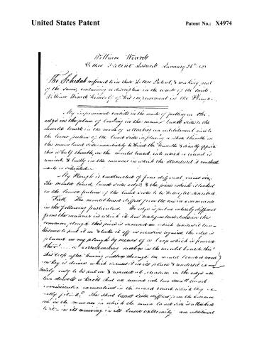
Page 2.
United States Patent
Patent No.: X4974
William Ward
This Patent Issued January 26th, 1825
The Schedule referred to in this Letter Patent, & making part of the same, containing a description in the words of the said William Ward himself of his improvement in the Plough.
My improvement consists in the mode of putting in the edge in the plan of locking in the main lands side to the mould board in the mode of attaching an additional side to the lower portion of the lands side in placing a whole thimble in the main lands side immediately behind the handle & directly opposite the whole thimble, in the mould board into which a round is received, & lastly in the manner in which the handle is constructed & detailed.
My Plough is constructed of four different pieces viz. the mould board, lands side, edge, & the piece which is locked on the lower portion of the lands side to be hereafter described.
First. The mould board differs from the one in common use in the following particulars. The edge is just as entirely different from the manner in which it has heretofore been done in the common plough. This piece is secured on which renders it unnecessary to put it on & take it off as occasion requires, the edge is placed on my plough by means of a loop which is fastened thru'... a corresponding notch in the mould board. thru' this loop after having passed through the mould board a hook on key is driven which secures it in its place & renders it extremely easy to be put on & removed off, likewise, in the edge are two dowels or knobs that are secured into two small round concave excavations in the mould board, which they exactly fit. The short lands side differs from the common one in the manner in which the main lands side is attached to it— in its receiving in its lower extremity one additional
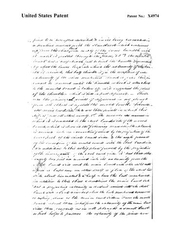
Page 3.
United States Patent
Patent No.: X4974
piece to be hereafter described, & in its being connected in a peculiar manner with the standard which continues up from this short side nearly of the same breadth with it until it passes through the beam, & is the mould board has a key pin just behind the handle & projecting by above the lower loop into which the extremity of the handle is received, that half thumb is for the reception of one extremity of the above mentioned handle or pin; this pin cannot be removed until the handle which is attached to the mould board is taken off, & it supplies the place of the thimble which is here in part deficient. — These are the principal points of difference in my plan from all others as regards the mould board. I mean the main thumb side; there are three points in which this differs from all others, namely, 1st. The manner in which it is connected to the short hand side of the mould board, which is done in the following manner, — the extremity is received into an excavated portion by the projection of the lower part of the short hand side. & the angle formed by the connection of the mould board with the short hand side. In addition to this resting place formed by the projection of the lower part of the short hand side, it had three other, namely two, and are received into its extremity from the short hand side with the main hand side also with its upper or lower over an other piece or piece of the short hand side about two inches & a half above the last mentioned, in addition to these three connections the main hand side had a projecting extremity or a small recess into the short hand side about an inch above the last mentioned connection or resting place of the main hand side. — From the mould board about three inches from the extremity of the main hand side there projects as in all plans a small knob which helps to preserve the extremity of the piece now
Page 4.
United States Patent
Patent No.: X4974
described in its place. Upon the outside of the main limb side B, at the lower part of it is placed an additional piece of nearly the same length, so as to have the same cover of the mould board. This piece is connected to the main limb side by two loops which pass through it, and two wooden keys at either end thereof to preserve the connection. This piece is about two inches & a half or three inches in breadth & about half an inch in thickness. This piece receives nearly all if not quite all of the wear which takes place in the use of the plough, on the ground side—just behind the mould board. The mould board above mentioned, is directly opposite to the heavy mould board above mentioned, between which the mould board is placed which keeps the mould board & the main limb side at the proper distance apart.—The mould board will be in between these two cast steel-boards, pieces about 7 inches. I insist of the loops mentioned in the specification above for the moulds of the plough, as they are adapted may be used.
In testimony that the above is a true description or specification of my above mentioned improvement, I have hereunto set my hand this 27th day of Dec. A.D. 1827
Witnesses
Wm. Copel……d
D. A. Watts
William H. H.
Received & Recorded June 7, 1841 & Exd. 1/1/76.
(913 words)
Published accounts: journal notice
Notice in the monthly list of patents
Journal of the Franklin Institute, vol. 5 (1828), p. 357 · View the page
In the plough; William Wiard, of Avon, Livingston County, New York, January 26.
About this record
- Patentee
- DATAMP
- Date
- the Name and Date index of patents, DATAMP, USPTO records
- Invention
- DATAMP
- Listed in
- the Name and Date index of patents, DATAMP, USPTO records, Jim Shaw's X-patent list, the Journal of the Franklin Institute, the Mirror of the Patent Office (1828), S. A. Elliot's printed list of patents, Burke's List of Patents (1847)
- The Mirror of the Patent Office's supplementary list gives the same patent.
- S. A. Elliot's printed list of patents gives the same name and date.
- Burke's 1847 Patent Office list gives the same patent.