

Drawings and documents
USPTO scan
The patent as scanned by the USPTO
-
 Page 1
-
 Page 2
-
 Page 3
-
 Page 4
-
 Page 5
-
 Page 6
-
 Page 7
-
 Page 8


U.S. Patent and Trademark Office · Google Patents
Show the transcription Hide (2,266 words)
Machine transcription (LightOnOCR) of the pages as scanned by the USPTO, most of them the handwritten copies made when the records were restored after the 1836 fire. Not checked; it can misread handwriting, so compare it with the scan.
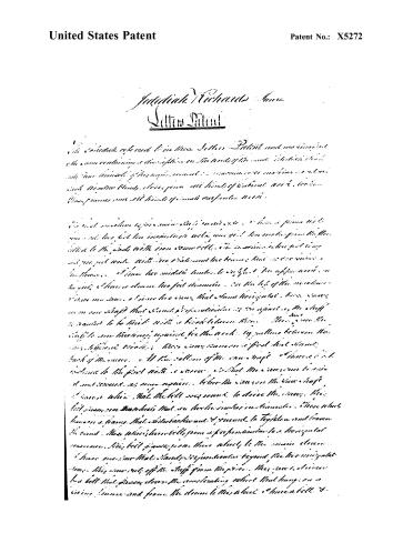
Page 2.
United States Patent
Patent No.: X5272
Johndiah Richards
Letters Patent
The Johndiah referred to in these Letters Patent and mentioned in the Specification is a Machine for Milling the Surface of Metal or Wood with Circular Blades, Saws, Files, All Kinds of Cutting Tools, Tools, Frames, and All Kinds of Small Workshop Tools.
The said machine is provided with a frame with a shaft for the milling tool, with a gear wheel for the shaft, with a belt for the gear wheel, with a pulley for the belt, with a motor for the …
Page 3.
United States Patent
Patent No.: X5272
when the swing is brought back by a handle it tightens the lower band and gives motion to the swing to hold the staff to be slid off. I have a new image with two head blocks that are let out & taken up to the length of the piece to be swung by means of a rod that is fastened. I have the head blocks by a screw at each end to take up the head block, to let them out as they may require. The head blocks are made of iron 16 inches long & ten inches wide & one half inch thick. The upper head block is perforated on one side. There is a piece in the head block, one inches wide, using higher than the one that connects the two feet of the head block, on the right hand head block there is a slide, on the one of the side I have a handle that is fixed to stand to the head block holds the piece when moving. When the piece is moved to swing the handle it is fastened on the inner edge of the head block. I have a groove to lay on the piece at each end the head blocks are on rollers. These rollers lie on the top surface of the frame.
The second machine is for drawing, it is about 3 feet long, the first is 6 inches wide. The first three feet are made high. There are two posts, four long posts and three short wide ones that are connected all together with iron bolts. There are two beams the first piece is on the first four inches from the bottom. The wheel on the main beam is the first piece is connected with an iron rod & staff. The crank is in the form of a Y with two square notches at the end of the Y for the stick to pass through. The stick is held in the crank at any given length to be two spaces. The staff is hung on the two left hand posts, one on each side at the end of the stick. The bottom is attached to a stick that goes on the back part of the machine. This stick is attached to a beam with a tongue & groove that holds the stick steady. This side is horizontal with the crank & there are two moving shafts of iron at the end of the stick. The stick runs on these shafts with two wheels on each shaft one eight inches and the other nine inches. There are belts connected to these & attached to the stick to move it up & down. The belt is to tighten the belt on the two wheels. There are belts fastened that lead to the frame for
Page 4.
United States Patent
Patent No.: X5272
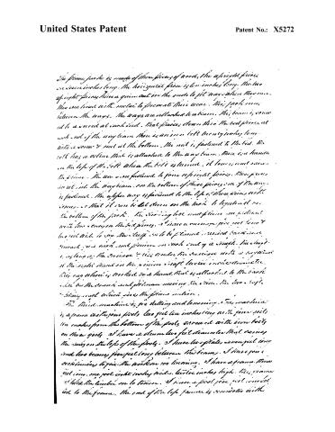
The frame piece is made of three pieces of wood, the upright pieces are seven inches long, the horizontal piece is ten inches long. The two upright pieces have a groove cut in the ends to fit ways where they run. They are fixed with metal to prevent their wear. This jack is between the ways. The ways are attached to a beam. This beam is secured to a wood at each end. That frames down this the bed piece, at each end of the way beam there is an iron bolt twenty inches long with a screw & nut at the bottom. The nut is fastened to the bed. The bolt has a collar that is attached to the way beam. There is a handle on the left of the bolt when the bolt is turned, it lowers and raises the frame. The ways are fastened to four upright pieces. These pieces are set into the way beam. On the bottom of these pieces one of the ways is fastened. The upper way is fastened to the top of these pieces with screws, so that it can be let down on the track to tighten it on the bottom of the frame. The sliding lock and frame are fastened with two screws on the bed pieces. There is a carriage piece just below the bed and to say the staff is to be fastened. Behind said frame is a shaft and pinion on each end of a shaft. The shaft is supported by the carriage & this under the carriage with a spring at the right hand on the pinion shaft located in the carriage. This way wheel is locked so a hand that is attached to the back side by the carriage and pinion moving the frame. The two staff things and which give the frame motion.
The third machine is for stalling and larning. This machine is a frame with four posts, two feet ten inches long with four rails, the makers from the bottom of the posts secured with iron bolts on those posts. I have a beam two feet diameter that carries the rails on the top of the posts. I have two plates seven feet long and two beams, five feet long between the beams. I have four cross timbers to give the work on the larning. I have a frame three feet long, one foot eight inches wide, twelve inches high. This frame I hold the timber on to tenon. I have a post, five feet long bolted to the frame. The end of the left frame is connected with
Page 5.
United States Patent
Patent No.: X5272
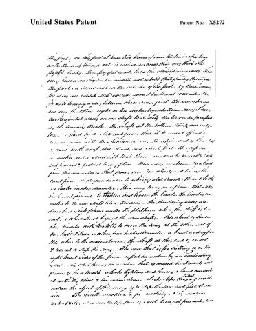
This foot. On this foot I have two pieces of iron twelve inches long with the ends turned out to receive a screw that goes through the foot's body. These foot's heads hold the shoulder's screws. These screws have a notch in the middle and a bolt that passes through the foot. It is screwed on the outside of the foot. By these means the screw can twist and turned around back and forward. The place to turn any screw between these screws. First the screw has one over the other eight or ten inches beyond these screws. I have two horizontal bars on one shaft that slits the iron as far apart as the screws are. The shaft at the bottom stands one inch below. It is fixed by a bolt and proves that it be moved off and on to come in and the iron is held in place. The upper end of this shaft is fixed with a screw that stands on a short foot. This foot has a notch and a screw that there are two to be inserted back and forward & fastened to any place. These two screws have been from the main stem that passes over two wheels and below the hand from a perpendicular to a horizontal course. These wheels are twelve inches diameter. Then they hang on a frame that they can be adjusted to tighten and loosen the band. The band is connected to the main shaft below the screw. The shoulder's screws are close but still placed under the platform when the shaft is turned. A wheel direct beyond the screw shafts. This wheel is six inches diameter with two teeth to carry the screw at the other end of the shaft. I have a wheel four inches diameter. A band leading from this wheel to the main drum. The shaft at this end is turned & turned to stop the screw. The screw that is for drilling is on the right hand side of the frame except no motion by an accelerating wind. This wheel turns on a main that is moved backwards and forwards for a handle which tightens and loosens a band connected with this wheel & the main drum which stops the gear in its motion. The object of this screw is to stop the screw and give it motion. The gear the machine is for working. This machine has two parts. At one end the left there are yet three feet four inches long
Page 6.
United States Patent
Patent No.: X5272
Page 7.
United States Patent
Patent No.: X5272
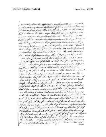
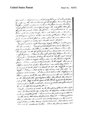
proceed to be so lined it moves back out of the way, it is brought forward by a spring. The tiles are laid across the bed piece to intersect by this bed piece and the notches are made in the piece in once handling back of the bed piece notches to gauge the ends of the tiles from the gate downward. I have the platform. It is attached to a track below with iron inches except the cross which is low in the chain, the 4 hangers on a frame within six inches of the piece. This piece is fixed in journal to it put in motion from the main drum it is stopped and put in motion by a handle with the foot.
The gypsy machine is for lowering rough stelling & making pins. For this machine I have four posts two feet ten inches high four feet ten inches from the bottom on those girts I have a cross bar bed steamer on the top of the posts I have two plates one foot wide except the frame. I have two beams five feet long between the beams I have five foot timbers to hang the work to in the right side of the frame I have a rough stelling saw on the back end of the frame I have a saw for cutting timber to the length. This saw is stopped and set in motion by a string & an accelerating wheel. It is managed by the foot & a handle to cut the staff to any given length. I have a stick with a slope at one end this stick is girdled with a screw. I have a block to hold the staff against that is square with the saw that moves over the saw with a pin in the block for the saw to pass through this block the straight side of the staff is held against this block is guided by two pieces running from to the outside running each side of timber, it has in the left timbers of the frame.
The pin machine is made with three pieces of timber three by four inches the two posts twenty inches long the left piece sixteen inches from on the inside of the posts I have a groove the gate runs in that carries the pieces that drives the pin from this gate I have a pinion that is attached to a crank one inches except on the cross shaft I have a chain twenty inches diameter that moves with that and the machine in motion. When the pin is made I have
Page 8.
United States Patent
Patent No.: X5272
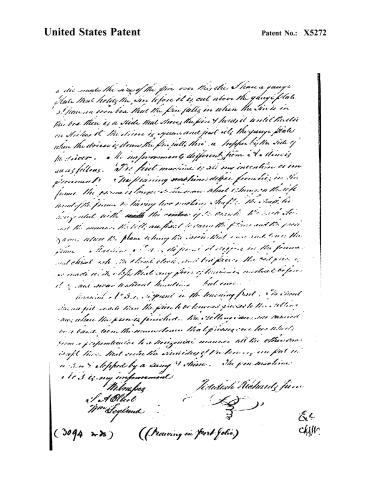
a die made the size of the pin over this die. I have a gauge plate that holds the pin before it is cut above the gauge plate. I have an iron box that the pin falls in when the die is in this box. There is a slide that moves the pin & holds it until the die strikes it. The slide is square and just sits the gauge plate when the die is down the pin falls thru a hopper by the side of the die. The improvement is different from a 4. This is as follows. The first machine is all my invention as an improvement. The pinning machine differs from this in the frame. The frame is longer & the man wheel & hanger on the left hand of the frame by having two moving shafts. The shaft is being used with the center of the wheel. The wheel is not the man. The lifts are fixed to raise the frame and the pins go on when the plane is hung the wheel that runs and turns the frame. The machine is 4. It is different & differs in the frame and wheel. The wheel does not turn the pin. The wheel is made with the help that any piece of timber is made before it is cut over without handling but once.
The 3. is different in the turning part. The wheel does not move when the pin is to be turned. The turning is done where the pin is finished. The turning is done on a band from the man wheel that pinning is done which from a perpendicular to a horizontal manner all the other one is put there that under the assistance of the turning is put in motion & stopped by a swing & chain. The pin machine is 3. is my improvement.
Witnesses
J. A. Elliot
Wm. Seyland
J. Arthur Richards, Jr.
(3094 2-25) (Drawing in Portfolio)
Ex.
Clyr.
Published accounts: journal notice
Notice in the monthly list of patents, with remarks
Journal of the Franklin Institute, new ser., vol. 3 (1829), p. 119 · View the page
10. For machinery for making Window-sash, Window-blinds, Doors, Fence, all kinds of cabinet-work, Looking-glass frames, and all kinds of small carpenters-work; Jedediah Richards, jr., Elbridge, Onondago county, New York, November 12.
Remarks. This is a machine to saw, plane, and mortise stuff for sash, and other purposes. The description is too obscure and incoherent to convey a correct idea of it, whilst it appears to resemble, in many particulars, other machines which have been heretofore made for similar purposes. The patentee has not informed us what he claims as new, and we are consequently left to infer that he considers the whole as such.
About this record
- Patentee
- DATAMP
- Date
- the Name and Date index of patents, DATAMP, Burke's List of Patents (1847)
- Invention
- DATAMP
- Listed in
- the Name and Date index of patents, DATAMP, USPTO records, Jim Shaw's X-patent list, the Journal of the Franklin Institute, Burke's List of Patents (1847)
- The sources give different dates; the date shown is the one most of them agree on.
- The Franklin Institute's journal confirms the date shown.
- Burke's 1847 Patent Office list gives the same patent.