

Drawings and documents
National Archives restored drawings: drawing
J. Thorp's Patent Drawing for a Can Spinner

National Archives, Restored Patent Drawings (Record Group 241) · Full-size scan at the National Archives · Catalog record
Show the text on the drawing Hide (87 words)
Words on the drawing as machine-read by the National Archives; not checked. Useful mainly for searching.
/1- 118. SPINNING. Tex / Shiming / [142] Throstles & Caps / J o THORP / Can Spinner / 5278-1 / Patented 25th Nor 1828 / Voly / A. Cup or can / B. Bobbin / C.Whorl / Sualso patent to / D. Spindle / C. sanforth Sep. 2, 1828 / E. Bobbin or Vibrating rail / F. Spendle rail / G. B and / Fy / ols / Strickland Del' / Patent office March 31ˢᵗ1841 / Made under the direction of the commissioner of patents / in conformity with ach of 3 March 183ry / Menry / Commissioner of patents
USPTO scan
The patent as scanned by the USPTO
-
 Page 1
-
 Page 2


U.S. Patent and Trademark Office · Google Patents
Show the transcription Hide (133 words)
Machine transcription (LightOnOCR) of the pages as scanned by the USPTO, most of them the handwritten copies made when the records were restored after the 1836 fire. Not checked; it can misread handwriting, so compare it with the scan.
Page 1.
No Printed Specification Available
5278X
J. Thorp.
Ring Spinning.
Patented Nov 20, 1828.

Page 2.
United States Patent Office
PTO - BOYERS, PA Duty Station
MISSING PAGE TEMPORARY NOTICE
PATENT # 5278X FOR ISSUE DATE 11-20-1828
HAS BEEN SCANNED, BUT WITH MISSING PAGE(S). UPON RECEIVING OF MISSING PAGE(S), THE ENTIRE DOCUMENT WILL BE RESCANNED.
PLEASE CALL IMAGE DATA ADMINISTRATION STAFF OF 557-6154 IF YOU HAVE A QUESTION. ASK FOR DAVE GROOMS, ANITA YOUNG OR POLA JONES.
THIS NOTICE IS FOR THE MISSING PAGE CONTAINING:
COLUMN # All Text
Data Conversion Operation
Boyers, Pa
Published accounts: specification
Specification printed in the Journal of the Franklin Institute
Journal of the Franklin Institute, new ser., vol. 4 (1829), p. 65 · View the page
Text of the specification as printed in the Journal, from OCR; not proofread.
Specification of a patent for an improvement in Spinning of Filling, and Slack Twisted Yarn, called the "Can Spinner." Granted to JOHN THORP, of Providence, Rhode Island, November 20, 1828. THIS improvement consists of a cup, or can, placed on the top of a dead, or still, spindle, around the surface of which the yarn revolves, being drawn by the bobbin as it twists and receives it. This cup, or can, answers the purpose of the common flyer, in keeping the yarn at a proper distance from the bobbin, and in guiding and distributing it thereon. The bobbin may be either a weaver's bobbin, or a common spinning bobbin, at the option of the manufacturer, and turns on the spindle, receiving its motion from a whorl, which also turns on the spindle, and with which it is connected at its base, by two pins, or studs, extend extending upward from the whorl, and entering two corresponding holes, or mortises, in the base of the bobbin, the whorl being banded gives positive motion to the bobbin. The bobbin rail is similar to the one in common use, excepting that it is made to steady the spindles by having the holes through which the spindles pass, of the same size as the spindles. It vibrates like the bobbin rail in common machines, and on it the whorl is set, obeying the motion of the rail, moving the bobbin up and down on the spindle, and spreading the yarn over the whole length of the bobbin, the lower edge of the cup, or can, being the guide. The rail to which the spindles are confined, or what may be called the spindle-rail, is a plate of cast-iron. In this rail are scores, which exactly fit the spindles, and by which, with the assistance of an eye, or clasp-bolt, they are kept perfectly steady; and by these bolts the spindles can easily be adjusted, and raised or lowered so that the lower edge of the cup, or can, which is the guide of the yarn, may suit the filling of the bobbin. The cup, or can, rests and is hung upon a shoulder at the top of the spindle, and its cavity is sufficiently large to admit the bobbin. This can be lifted off and put on again with ease. must be taken off to change the bobbins, and to mend or piece the yarn when the bobbin is in the can. In finding broken ends, or in piecing the yarn, the bobbin is lifted by the thumb or finger, from the pins, or studs, that connect it with the whorl, and the whorl is allowed to run while the yarn is put in a proper position to be mended; then the thumb, or finger, is withdrawn from the bobbin, and it falls to its proper place, connecting itself again with the whorl. When spindles are placed close to each other, it may be necessary to surround each cup, or can, with a cylindrical, or semi-cylindrical tube, VOL. IV. No. 1.-JULY, 1829. 9 It THORP'S Ring Groove Spinner. to prevent the yarns from interfering as they pass round their respective cans. JOHN THORP. A, cup, or can. References to Fig. 3, Plate 1. B, bobbin, which may be either a spinning bobbin or a weaver's bobbin. C, whorl, on which the bobbin stands, and with which it is connected. D, spindle. E, piece of the bobbin, or vibrating, rail. F, piece of the spindle rail. G, band (lettered C.) H, eye, or clasp-bolts, which secure the spindles (not lettered.) The yarn is seen leading down from the rollers of a common spinning frame. The can, A, rests on a shoulder at the top of the spindle, and can be taken off and put on with ease. Around the surface of this can, the yarn revolves; being drawn by the bobbin, as it twists and receives it. The lower edge of the can is perfectly smooth, and serves to guide and distribute the yarn on the bobbin. The bobbin, B, stands on the whorl, C, and is connected with it by two pins, or studs, that extend upward from the whorl, entering a hole, or mortise, in the base of the bobbin; and the whorl, being banded, causes the bobbin to have a positive motion. The whorl, C, sets on the bobbin, or vibrating rail, E, and turns on the spindle, moving up and down, obeying the motions of said rail, spreading the yarn over the whole length of the bobbin. The holes in the rail, E, through which the spindles pass, are of the same size with the spindles themselves; by which means they are kept steady. The rail, F, is a stationary plate of cast-iron, to which the spindles are confined. The bolts, H, through which the spindles pass, have a screw-nut on the backside of the rail, F, by which the spindles are drawn close to the rail, and held perfectly steady. When the spindles are placed close to each other, it may be necessary to surround each cup, or can, with a cylindrical, or semicylindrical tube, to prevent the yarns from interfering as they pass round their respective cans. Description of an improvement in spinning, called the "Ring Groove Spinner," for which apatent was granted to JOHN THORP, of Providence, Rhode Island, December 31, 1828. THE drawing and references which accompany this description, render it unnecessary to give the specification at length; we, therefore, will briefly state the nature of the invention. THORP'S Ring Groove Spinner. The common flyer is dispensed with in this improved mode of spinning, a ring being substituted for it, for the purpose of distributing the yarn upon the bobbin. The ring is sufficiently large to admit of the bobbin, with the yarn wound thereon, passing through it. Upon the surface of this ring the yarn revolves, being drawn by the bobbin as it twists, and receives it, and serving at the same time to keep the yarn at a proper distance from, and to distribute it upon, the bobbin. The ring is placed in a circular groove, in a circular plate, H, Fig. 4. This plate encompasses the bobbin, and may be made to vibrate over it by the motion of the rail to which it is attached, or the spindle and bobbin may be made to vibrate, as may be preferred. The lips that form the groove, are of a circle smaller in diameter than the ring, in order to retain it in its place. The depth of the groove is such as to allow the ring to yield to the pressure of the yarn. The ring thus fitting loosely, permits it to yield on either side, so as to allow a space for the revolving of the thread between it and the groove, whilst the friction which it sustains, causes it to wind sufficiently tight upon the bobbin. The plate is opened on the front by a narrow saw kerf, running obliquely through it from right to left, which allows a free passage of the yarn from the outside of the plate to the ring. -The spindles differ from others only in their being shorter above their upper bearing; they have a collar on them, on which the bobbin sets, and with which it is connected by two pins, or studs, extending upward, and entering two corresponding holes in the base of the bobbin. Either a common, or weaver's, bobbin may be used, and may be readily taken off and put on to the spindle. When constructed for a weaver's bobbin, the collar on which the bobbin rests has a spiral spring under it, and when the yarn breaks it can readily be pressed down, and joined, without taking the bobbin off. When on a common spinning bobbin the yarn breaks above the plate and ring, it must be taken off, in order to mend, or piece the yarn. The bobbin that is intended for the shuttle, has its shaft in two parts, being split nearly from point to head, which causes it to bind well when crowded on to the tongue of the shuttle. References to Fig. 4, Plate 1. A, is the bobbin-rail, B, the spindle rail, C, the foot rail, D, the spindle. } of a common spinning frame. E, the bobbin, connected with the collar, F, by pins, or studs. F, a collar which slides on the spindle, and is connected with it by the spiral spring, I, which being confined to the collar at the top, and to the spindle at the bottom, causes the collar and spindle to turn together. G, a box which forms the upper bearing of the spindle, D, and in which it turns. H, the circular plate, bolted to the rail, A, and which has in it a groove, in which the ring (represented by the white line,) is loosely THORP's Cap Spinner. placed, allowing the yarn to revolve around its surface. The opening of the plate is also seen. The shaft of the bobbin, E, is seen split for the purpose of spreading and tightening it. The yarn is shown as it comes down from the rollers of a common spinning frame. The detached figure, H, represents a ground view of the circular plate, and of the ring resting and playing upon J. Description of an Improvement in Spinning, denominated the "Cap Spinner," being an improvement on the Ring Groove Spinner. Patented by JOHN THORP, of Providence, Rhode Island, January 21st, 1829. THE circular plate described in the ring groove spinner, is in this improvement made deep, say about an inch, so as to form a tube, and is placed and confined like the plate in the former. There is in this apparatus, a part called the cap, which answers the purpose of a ring, in the ring groove spinner. This cap rests upon a rim which projects inwards about an eighth of an inch, on the lower edge of the tube; this cap is made in the form of a liquor tunnel, with its nose upwards; it encompasses the bobbin, which may be a common weaver's, or shuttle, bobbin, split in the manner and for the purpose described in the ring groove spinner. The loweredge of the cap, which acts on the yarn, is perfectly smooth and polished. When the bobbin is a common spinning, or throstle, bobbin, the cap is of one diameter throughout, forming a straight tube of the length of the bobbin, with a head at the top; which head is pierced through its centre, which steadies it on the spindle, or the tube may be considerably less in length, open at both ends, so as to allow the bobbin to pass up and down through it. A thin, round, flat piece of metal, larger in diameter than the largest diameter of the cap, with a tube long enough to steady it, is placed horizontally on the top of the bobbin, or spindle, so that it can be removed and replaced with ease. Small polished notches on the edge of this plate, assist the yarn in revolving round the cap. The plates and caps may be made of any suitable metal, and may be about one-sixteenth of an inch in thickness. Fig. 5th, plate 1, represents the cap spinner. A, A, A, are pieces of common step-rail, spindle-rail, and vibratingrail. B, a spindle of the common kind, excepting that it has no flyer. C, the whorl, confined to the spindle. D, a box, being the upper bearing of the spindle, and in which it turns. E, a common weaver's or shuttle bobbin, crowded on the spindle. F, the thin, tubular, circular plate. G, arms belonging to, and extending back from, the plate. H, an arm, or stud, extending upwards from the vibrating rail. THORP'S Improvement on the Can Spinner. I, A pin, or pivot, passing through the arms G, and stud H, forming a joint. K, the conical socket, called the cap. L, the thin, flat, notched, circular plate, fixed on the spindle. The yarn is represented as it comes down from the rollers of a common throstle, or spinning frame. The plate F, is about one-eighth of an inch thick, about an inch deep, and about one and three-eighths of an inch in diameter within. It is connected to the vibrating rail by a joint, as represented in the plate at G, H; the pin I, forming the pivot. To find the end of the yarn when broken, the plate is lifted up, and the end of the yarn taken from the bobbin below the plate, and the plate being open in front, the yarn is then passed through it to the cap; or the cap may be lifted for the purpose of mending, or piecing the yarn, in which case the plate may be bolted to the vibrating rail, and need not be open in front, as represented in the drawing. The wood cut in the margin, represents the cap when constructed in the manner best suited for spinning on a common throstle bobbin, or a bobbin with two heads. In this the cap is taken off, for the purpose of mending, or piecing the yarn, as above described.
Published accounts: specification
Specification printed in the Journal of the Franklin Institute
Journal of the Franklin Institute, new ser., vol. 4 (1829), p. 130 · View the page
Text of the specification as printed in the Journal, from OCR; not proofread.
Specification of a patent for an improvement in Spinning Cotton Yarns and Roping, which improvement is called "THORP'S RUNNING CAP SPINNER." Granted to JOHN THORP, of Providence, Rhode Island, June 13th, 1829. THIS improvement in constructing the machinery for spinning, and in spinning cotton yarns and roping, consists of a short conical, running cap, the shape of which is similar to that of a tunnel with its nose downwards, hung and supported at the top of a live or running spindle. The use and functions of this cap, are, to keep the yarn and roping at a proper distance from the bobbin; also, to direct and distribute it thereon. The yarn is not connected with the cap, as in the common flyers, but it is allowed to revolve around the surface of said cap, yielding to the resistance of the atmosphere, causing it to fall back of the cap, and wind on the spool or bobbin, the lower edge of the cap being the guide. The cap should be placed near to the guide wire, so that as little length of the yarn or roping as possible be exposed to the atmosphere. The nose, or shank, of said cap is penetrated by the top of the spindle, which nicely fits it, and is held fast to its place by a screw, or a pin and slot, similar to the common method of fastening a bayonet to the end of a musket, or by a catch like that of a bit stock, or in any other suitable way. The following dimensions are suitable for spinning, on a weaver's, or shuttle bobbin; and when other bobbins are used, the dimensions must be varied to suit them. The whole length of the cap, from the top of its nose, or shank, to the lower edge of its conical part, or brim, should be about two and three-quarter inches, and the length, or depth, of the conical part about one inch. The diameter of its brim should be about an inch and one-quarter. The hole, or cavity, of said cap, after leaving the conical part, should be larger than the bobbin shaft, (which is hereafter described,) and continue of an equal diameter about the distance of an inch and a quarter, in which the top of said shaft will traverse, and the remainder of the nose above is nicely fitted to the top of the spindle, as above described. At the top of the conical part of its cavity are fixed a set of pins, say four, projecting inwards, so that their ends reach the spindle, for purposes hereinafter described. The thickness of the cap should be about the eighth of an inch; said cap may be made of iron, or any hard suitable metal. The spindle, and its situation in the frame, is like that of the common throsel, receiving its motion from the same source as that of the throsel spindle. The length of the spindle above the upper bearing, may be according to the desired length of the bobbin, which for a common shuttle, or weaver's bobbin, ought to be about seven inches. 'The bobbin (the body or shaft of which is a tube of thin sheet iron, or brass, or tin, or, may be, wood,) traverses on the spindle, and turns with it. Said shaft is smooth on the outside, and its head moveable on its body. The upper end of said body, or shaft, which will remain in the cap, has in it four slots, or mortises, extending down and running parallel with the spindle; in these mortises the aforesaid pins traverse; or, in other words, the mortises give liberty for the bobbin to traverse on the spindle. The pins assist in crowding, or pressing, the yarn or roping down the bobbin; they also compel the bobbin to turn with the spindle. In the commencement of filling the bobbin, the head is slipped up to the top of its body, (which will be in the cap,) and by means of a spring fixed in the head, and crowding against the body, holds said head wherever it is placed. The head, together with the roll of yarn or roping, is crowded down the bobbin as fast as it fills with yarn-this is effected by the conical point of the roll of yarn, or roping, crowding within and against the conical sides of the cap at every vibration, or elevation, of the bobbin, alternately condensing the yarn or roping, and crowding it down the bobbin, until the bobbin is filled the whole length-the bottom of said body, or shaft, will set on the vibrating rail (or lifter, so called,) and will vibrate for the purpose of forming the said spire or roll of yarn, or roping. Said roll, or spire, may be slipped off from said bobbin, and placed on another of the ordinary kind, or on to a suitable tongue that may belong to the shuttle, and save the expense of fixing more than one set of bobbins in the above described manner. The bobbin, spindle, and cap, all run together, each one performing the same number of revolutions. It is necessary that there should be something to check, or obstruct, the progress of the yarn while revolving, such as the fibres of woollen cloth, or the pressure of a gentle spring touching the said cap. The use of this is to produce a friction on the yarn, causing it to fall back of the cap, and wind tighter on the bobbin; also to prevent the yarn from catching, and winding round said cap. From a number of different ways in which this can be effected, I have selected the following, viz: a thin, flat ring or plate, of iron, brass, wood, or any other suitable substance; the diameter of the hole through it, should be the same with that of the cavity of the cap at the brim, and the diameter of its outer circle, or whole substance, should be greater than that of the outside, or brim of the cap. The flat surface on the upper side of said ring, or plate, should be smooth, or may be covered with cloth, leather, velvet or any other suitable substance; said ring, or plate, is situated under the broad brim of said cap, and its upper surface is pressed lightly, against the lower flat surface of the cap, by a light spring, or weight. Between these two surfaces the yarn revolves, and by increasing or decreasing the pressure, the yarn is made to wind tighter, or not so tight, on the bobbin. Said ring has a broad, thin, elastic arm, or shank, belonging to it, which acts as the spring to press said ring against the cap, and by which the ring is confined to a rail that stretches along the frame, back of the spindles. It is necessary that the ring, or plate, be open in front, so as to give the yarn a free passage to the cap. To mend, or piece, the yarn, the following rules should be observed; the spindle is stopped by taking hold of it below the upper bearing, with one hand, while, with the other, the cap is lifted off, and held between the fingers; and with the thumb and forefinger of the same hand a sufficient length of yarn is drawn from the bobbin, and then the cap is replaced on the spindle, and the yarn cast into the guide wire, and the hand withdrawn from the spindle, and the thread pieced-or, instead of lifting the cap off from the spindle, for the purpose of piecing the yarn, it may be done as follows, viz: the lifter on which the bobbin, or the bobbin's shaft, or body, sets, may be a spring, or may be constructed with a joint, and a handle in front, which can be taken hold of and pressed down, bringing the point of the roll of yarn, or roping, below the cap, and the upper end of said shaft, or body, below the above mentioned pins, which will allow the bobbin to turn on the spindle, so that the yarn can be drawn off and pieced. When the said lifter is pressed down, it may come in contact with the spindle, and stop it, while the yarn is put in readiness to piece-or said lifter may be held up to its place by a spring catch, and when the catch is withdrawn, the lifter will fall, giving the same opportunity to piece the yarn as above described. What I claim in this improvement as my invention, and in which I desire an exclusive property, is-the short, conical running cap, and the peculiar manner in which the yarn is conducted to the bobbin-the moveable head above described-the method of condensing the yarn, or roping, by crowding it into the cap, as above described the method of beginning at the top, or point, of the bobbin to fill it, as above described the crowding or slipping, the roll, or spire, of yarn or roping, down the bobbin as it fills-also the above described manner of producing a friction on the yarn that causes it to wind tighter on the bobbin-and the application of all, or any, of the above stated improvements to any kind of spinning where they may be useful. DESCRIPTION OF THE FIGURE. JOHN THORP. A. The spindle. B. The whorl. C. the step. ing to the spindle. D. The box that forms the upper bearE. The end of the vibrating rail. F. The lifter. G. A pin which has in it a notch that holds the lifter up to its place. N. A pin that is confined to one end of a slide, or spring catch, that works under the lifter, the under end of which catches in the above mentioned notch, holding the lifter up to its place. I. The shaft, or body of the bobbin. J. The head of the bobbin, which is moveable on its body. K. The ring, or plate, that presses up against the cap and yarn, causing the yarn to wind tighter on the bobbin. L. The running cap. M. The guide wire. The yarn is seen upon, and extending above, the bobbin. M L NIF D B A C K G E
Published accounts: journal notice
Notice in the monthly list of patents, with remarks
Journal of the Franklin Institute, new ser., vol. 3 (1829), p. 121 · View the page
16. For Knot Shuttles, and machinery by which they are operated, for the purpose of tying knots to be applied to the making of weavers' harnesses, seines, nets, netting, fringes, &c.; John Thorp, Providence, Rhode Island, November 20.
Remarks. It was intended to give the specification of this invention entire, with an engraving from the well executed drawing which accompanies it, but the inventor mentions, in a letter recently received from him, that he has found several alterations necessary, which will vary it so materially as to require a new patent. When this is completed, we will fulfil our first design. VOL. III.-No. 2. - FEBRUARY, 1829. 16 American Patents for November, with Remarks.
Published accounts: journal notice
Notice in the monthly list of patents, with remarks
Journal of the Franklin Institute, new ser., vol. 3 (1829), p. 122 · View the page
18. For an improvement in the Spinning of Filling and Slack Twisted Yarn; John Thorp, Providence, Rhode Island, November 20.
Remarks. This will accompany the foregoing.
Published accounts: journal notice
Notice in the monthly list of patents, with remarks
Journal of the Franklin Institute, new ser., vol. 4 (1829), p. 62 · View the page
1 Specification of a patent for an improvement in Spinning and Twisting; consisting of a Whirling or Rotary Ring, and a Revolving Hook, (intended to answer the purpose of the common flyer,) and the connexion of the Bobbin and Spindle. Granted to JOHN THORP, of Providence, Rhode Island, November 20, 1828.
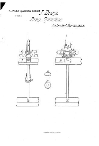
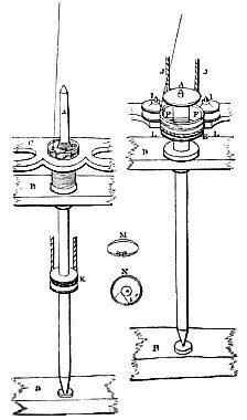
Remarks. A WHIRLING, or rotary ring, and a revolving hook, are used in the place of the common flyer, to keep the yarn a proper distance from the bobbin, and to guide and distribute it thereon. The ring segment, or section, or piece to which the hook is confined to hold and steady it, moves in a circular groove, or grooves, formed in a circular plate, that encompasses the bobbin. Said hook is placed where the lower extremity of the flyer, in common spinning frames, moves. The bobbins, being connected with the spindles, and moving positive therewith, drag the ring, segment, or section, or piece to which the hook is confined, causing the hook and the piece to which it is confined, to revolve in said groove, or upon a lip, or rim, projecting from, and belonging to said plate, the friction of which produces that tensive draught requisite to wind the yarn on the bobbin. The above mentioned ring may be made of small wire, the ends of which may be so doubled as to form the hook; or the hook may be made of a piece of steel, and confined to each end of the wire, or the piece of steel itself, of which the hook is formed, may be made to slide loosely around in said groove, or upon a rim or lip, and thereby dispense with the ring. The spindles have in them a collar, from which two studs, or pins, extend upward, containing a mortise, or hole, in the base of the bobbin, by which the spindle and bobbin are united, causing the bobbin to move positive with the spindle, twisting the yarn; and the yarn being placed in the hook, the hook is dragged around in said groove, and falls back of the bobbin, winding the yarn on it as fast as delivered from the rollers of the machine. The bodies of the bobbins must be half as large again as those of the common kind, and may be greatly increased in length. The plate above mentioned, in which the groove is formed, may be a ring, or else a hole through the plate, encompassing the spindle, through which the bobbin vibrates. The above improvement can be used in the common throstle frames, by confining said plate to what is called the bobbin, or vibrating rail; in which case the hook will rise and fall for the purpose of distributing the yarn upon the bobbin; or the plate may be attached to the spindle, or stationary rail, and if so attached, the spindles and bobbins must rise and fall for the purpose of distributing the yarn as aforesaid. It may be requisite, in some kinds of spinning, or twisting, to band the ring; in which case the plate will be unnecessary, and the rings made wide, say about an inch, and thin, and supported by friction pullies, so as to receive a band and motion from the cylinder or drum. In this case the hook is formed in the upper edge of the ring, to receive the yarn, and drag the bobbin, like the arms of the common flyer. The friction pullies are placed on studs, or pivots, which are arranged in a line, at equal distances, and are confined to either of the above mentioned rails, and are equal in number with the rings, and an additional one at the end of the row, to secure the outer ring. In forming the score in the pullies for the bands, two projecting rims are left, one at the top and another at the bottom of said pullies, which shut into two creases, or channels, formed in the ring, one at the bottom and the other about midway of the ring, serving to steady and keep said ring in its place. The score in the ring, which is intended for the band, being between the creases, and the pressure of the band on the ring being toward the pullies, also serves to keep the ring in its place. It is, however, necessary, where the rings are large, that they should have something to steady them in front, or opposite to said pullies, which may also be friction rollers, or studs. The objects of the above improvement are to dispense with the common flyer, and obtain greater speed than the arms of the flyer, and common operations of the bobbin will allow of, and to increase the length of the bobbins, so that a greater quantity of yarn can be spun before they require shifting, and to produce a more constant, even, and tensive draught on the yarn, than is produced in the common mode of spinning, and to render the trembling of the spindle, occasioned by wear, less injurious. References to Plate 1. JOHN THORP. A, Fig. 1 and 2, represents the spindle and bobbin. B, Fig. 1 and 2, a piece of the spindle, rail, and step-rail. C, Fig. 1 and 2, a part of a stationary rail. D, Fig. 1, a circular plate. E, Fig. 1 and 2, a whirling, or rotary ring. F, Fig. 1 and 2, the revolving hooks. H, Fig. 1 and 2, the yarn. I, Fig. 2, friction pullies. J, Fig. 2, the band. K, Fig. 1, the band and whorl. L, Fig. 2, the creases, or channels, in the rotary ring. Description of Fig. 1. The spindle and bobbin, A, are connected by a couple of studs, or pins, extending upward from a collar on which the bobbin sets, entering a hole, or mortise, in the base of the bobbin, or it may be crowded snugly into the spindle. The rail, C, is a plate of cast-iron, having holes through it, in one of which the circular plate, D, is confined. In this last plate, is a groove, in which the rotary ring, E, is loosely placed, and allowed to revolve in said groove; to this ring, the hook F, is attached. The yarn being placed in the hook F, and the bobbin turning positive with the spindle, drags said hook and the ring, E, causing them to revolve in said groove. The friction of the hook and the piece to which it is attached, produces that tensive draught requisite to wind the yarn on the bobbin. Description of Fig. 2. The bobbin, A, stands loosely on the spindle, and allowed to turn on it, or the spindle turns, as the case may happen. The whirling, or rotary ring, E, has creases, or channels, in it, in which the projecting rims of the friction pullies shut, serving to steady and keep said ring in its place. The pressure of the band, J, on the ring, being toward the pullies, also serves to keep the ring in its place. Said ring receives motion from a cylinder, or drum. The hooks, F, receive the yarn, and drag the bobbin, like the arms of a common flyer. The spindle and bobbin, in both figures, must vibrate, in order to distribute the yarn over the whole length of the bobbins. Fig. M, represents a form in which the rotary ring and hooks (in Fig. 1,) can be made of the same piece of wire.
Published accounts: journal notice
Notice in the monthly list of patents, with remarks
Journal of the Franklin Institute, new ser., vol. 4 (1829), p. 64 · View the page
Fig. N, ground view of said ring; it being heaviest at c, causes a greater centrifugal inclination at that place, equal in force to the THORP'S Can Spinner for Filling, &c. counteracting draught of the yarn, which is from b to a; and as the bobbin fills, the counteracting draught diminishes, and friction increases, making the draught on the yarn more equal. Increasing or diminishing the weight of the hook, increases or diminishes the draught on the yarn. Specification of a patent for an improvement in Spinning of Filling, and Slack Twisted Yarn, called the "Can Spinner." Granted to JOHN THORP, of Providence, Rhode Island, November 20, 1828.
Remarks. THIS improvement consists of a cup, or can, placed on the top of a dead, or still, spindle, around the surface of which the yarn revolves, being drawn by the bobbin as it twists and receives it. This cup, or can, answers the purpose of the common flyer, in keeping the yarn at a proper distance from the bobbin, and in guiding and distributing it thereon. The bobbin may be either a weaver's bobbin, or a common spinning bobbin, at the option of the manufacturer, and turns on the spindle, receiving its motion from a whorl, which also turns on the spindle, and with which it is connected at its base, by two pins, or studs, extend extending upward from the whorl, and entering two corresponding holes, or mortises, in the base of the bobbin, the whorl being banded gives positive motion to the bobbin. The bobbin rail is similar to the one in common use, excepting that it is made to steady the spindles by having the holes through which the spindles pass, of the same size as the spindles. It vibrates like the bobbin rail in common machines, and on it the whorl is set, obeying the motion of the rail, moving the bobbin up and down on the spindle, and spreading the yarn over the whole length of the bobbin, the lower edge of the cup, or can, being the guide. The rail to which the spindles are confined, or what may be called the spindle-rail, is a plate of cast-iron. In this rail are scores, which exactly fit the spindles, and by which, with the assistance of an eye, or clasp-bolt, they are kept perfectly steady; and by these bolts the spindles can easily be adjusted, and raised or lowered so that the lower edge of the cup, or can, which is the guide of the yarn, may suit the filling of the bobbin. The cup, or can, rests and is hung upon a shoulder at the top of the spindle, and its cavity is sufficiently large to admit the bobbin. This can be lifted off and put on again with ease. must be taken off to change the bobbins, and to mend or piece the yarn when the bobbin is in the can. In finding broken ends, or in piecing the yarn, the bobbin is lifted by the thumb or finger, from the pins, or studs, that connect it with the whorl, and the whorl is allowed to run while the yarn is put in a proper position to be mended; then the thumb, or finger, is withdrawn from the bobbin, and it falls to its proper place, connecting itself again with the whorl. When spindles are placed close to each other, it may be necessary to surround each cup, or can, with a cylindrical, or semi-cylindrical tube, VOL. IV. No. 1.-JULY, 1829. 9 It THORP'S Ring Groove Spinner. to prevent the yarns from interfering as they pass round their respective cans. JOHN THORP. A, cup, or can. References to Fig. 3, Plate 1. B, bobbin, which may be either a spinning bobbin or a weaver's bobbin. C, whorl, on which the bobbin stands, and with which it is connected. D, spindle. E, piece of the bobbin, or vibrating, rail. F, piece of the spindle rail. G, band (lettered C.) H, eye, or clasp-bolts, which secure the spindles (not lettered.) The yarn is seen leading down from the rollers of a common spinning frame. The can, A, rests on a shoulder at the top of the spindle, and can be taken off and put on with ease. Around the surface of this can, the yarn revolves; being drawn by the bobbin, as it twists and receives it. The lower edge of the can is perfectly smooth, and serves to guide and distribute the yarn on the bobbin. The bobbin, B, stands on the whorl, C, and is connected with it by two pins, or studs, that extend upward from the whorl, entering a hole, or mortise, in the base of the bobbin; and the whorl, being banded, causes the bobbin to have a positive motion.
DATAMP: illustration
Illustrations from DATAMP

DATAMP (Directory of American Tool and Machinery Patents), via the Internet Archive · Archived DATAMP page
About this record
- Patentee
- DATAMP
- Date
- DATAMP, USPTO records, Burke's List of Patents (1847)
- Invention
- DATAMP
- Listed in
- the Name and Date index of patents, DATAMP, USPTO records, Jim Shaw's X-patent list, the Journal of the Franklin Institute, Burke's List of Patents (1847)
- The sources give different dates; the date shown is the one most of them agree on.
- The Franklin Institute's journal confirms the date shown.
- Burke's 1847 Patent Office list gives the same patent.