

Drawings and documents
National Archives restored drawings: drawing
William Woodsworth's Patent Drawing for a Planing Machine


National Archives, Restored Patent Drawings (Record Group 241) · Full-size scan at the National Archives · Catalog record
Show the text on the drawing Hide (897 words)
Words on the drawing as machine-read by the National Archives; not checked. Useful mainly for searching.
Sheet 1. Duplicate / 53151 / 143.. WOOD M / 2. GENERAL WORK MACHINES. / Andrews punfet / [173] Planing.
Sheet 2. In / Incem; Broath / John Yibson fother / Wilham Wordwi / City Horring ofalbough / Wlham Wordworth one of defindants in this cause, being / anlyhoom suith, that the Við thin obenoms, represent the / machmi for the ing tion the patent / 27 December, 1825, walfow tadto him, andeshid. arawings / are duplicates of those deposited on / the granting of the Patent / Swom tobefor this / Nolliam Wood / 6th dayotmarch, 1838 / When Sexthmick / Evirm Ciry / EVC / mbross ndrews
Sheet 3. $4 / Ephy of these sont If'ru Woodworth / 20 1845 Demberp July 20 28 / Planing machine / This was received at this office / Patented 27 Nec 1828 / andfiled Nov T14. 1842 / Enselended fo of years longer / Dublicate / CIA / 5315-X / [173] Planing. / 2. GENERAL WORK MACHINES. / 143. WOOD WORKING: / A.Andrews minket
Sheet 4. Ambri fondrews / Two York Fily
Sheet 5. MittiamMiodwerths Miodwerth's / (Copy.) / 5. / C. / 144 WOOD WORKING MACHINES. / 5315 / Planing and Matching. / Motebring / Planing Machine Sumber / Gat. Dec, 27/828 a7-182 / ICATION / Top view. / 5315-X / Patented 27 Z / DIVISION / References. / Duplicate / a. Axis of the rolary culting wheel / 2. Malionary head of ditto. / c Movable head of ditto / d. Knives. / e Carriage / f Rack / Pinion / oh. Grooving wheel. / side Elevation / i. Rabbiting wheel. / Satent Office 29. aug 1839 / Made under the Correction of the of Patents, in conformity with / act A of 3 3 MarchD 1837. / (Signed.) / Comm of Patents
Sheet 6. 143. WOOD WORKING. / 2. GENERAL WORK MACHINES. / [173] Planing. / CLASSIC / William Woodworth's / 5315-X / Plancing, C Machine. / Patented 21 Dec: 1828. / W.Noodworth / Dec, Dec,27,1825. / Top view. / References. / a axis of the rotary cutting wheel. / b Stationary head of ditto / C. Movea ble head of ditte. / d. Knives / e barriage. / Side elivation. / f. Rack. / Hd / 9 Aien / h. Grooving wheel / i. Rabbeting wheel / Benne delt. / Patent Office 29th Aug". 1839. / Made under the direction of the Commipioner Comm of Patents, in / comformity with act: 3d, March 1837. / Somm: Comm: of Patents
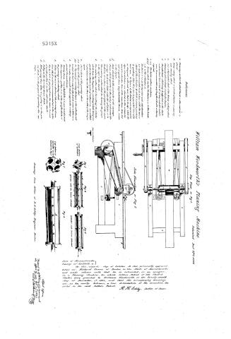
Sheet 7. 2, / 144 WOOD-WORKING 53/9 MACHINES. / Fast Planing and Mutching. / Widiam Woods rth's Planing Machine / Patented Decr / 5315-X / Top View or Fight. / References. / a Thecarriage on which the plank, board, or other material is / placed. / A., Rotary cutting wheel or cylinder ofknires or planing / and reducing wheel. / b. Axis korizantal shaft of the Rotary cutting wheel. / c. Stationary orfixed head ofçylinder knires / d. Morcable head, which may be adjusted on the shaft, / and confined bya scrow d, or anysuitable contrir- / ance, to accommodate anylength ofknife orknives / required. / C.C.l. The knires, cutters orplanes. / S.f.f. Screws which confine the knires P. e. to heads / c.d. of the cylinder A. / it's / The knires e C.C. in the top riew and side eleration / are each represented as in a line with the axis or / shaft of the cylinder; by which smeant practical / ly speaking, that they are in 0 parallel line with / Side Elevation or Fig 2 / said axis. In Figure 3, the knires are represented / as diagonal with said axis; that is to say; while the / edges ofsaid knires are situated zz the circumfer / ence of a cylinder, they: at the same time. form hel / ical or spiral lines longitudinally theron asseen / in the figure / 3 Rack attached to the underside of the carriage. / h. Pinion which operates in the rack and mores the / carriage back and forth under the cylinder, or to / the knires orcutters. or the periphory ofthe same. / & i. The revolring culter whool for forming the groore / in the edgre ofthe board. / k. The revolving entter whool for cutting the rebates / which form the tongrue, the revotring wheel heing com / Side of Wheel / On this second day of October D. 1841. personally appeared / posed of two wheels, orsels of cutters l.m, one of which / is placed directly orer the other, at the width of the tongue / apart. / Fig.5 / n. Axis (or shaft) (07 of the grooring wheel. / Fig. / Fig.4. / before me Richard Vrann of Boston in the State of Massachnsetts / and made solemn oath that he is interested, as an assignee / in a Planing Machine for which Letter's Patent of the United / States were granted William Woodworth, on the twenty seventh / day of December In 1828; and that the accompanying drawings / are, as he verily believes, a true deliniation of the invention des / H. Eddy, Justice of Peace. / O.O. Cutters of the greering wheel. / Crofs Section / p.p. See Figo.456,6,1. 05's convoting the heads ofthe cylinder, and / of Cylinder / to which the knires may be attached screws or bolts / S. The wooden framework which supports the working / Cylinder with the knives attached / Cylinder with knires detached / partsof the machinery. / st Stale of Massachusetts / County of Suffolk ss / cribed in the said Letters Patent. / t. Driring drum, from which belts и. r, pass to and around / their respectire pullies W, x. on the upright shafts of / rig 7. / Fig.3 / the grooring and rebating wheels. / y. Pulley on the axis orshaftz, of the driring drum, / Crofs Section of / from which motion is communicated tothe cylin. / Cylinder as.ex / der by a belt a', passing from the same, to, and / hibited in Fig.3 / arounda pulley on the cylinder shaft. / é Pulley, on the driring drum shaft. / d Belt passing from ditto, to a pulley B', on the pin. / ion shaft, for the purpose of operating the car / Patents Offices / riage. / Res tored by W.Eddy received al / Drawing's from Office of R.H.Eddy, Engineer Boston. / the office Oct 1841
Sheet 8. 144 WOOD-WORKING MACHINES. / Planing and Matching.
Sheet 9. Fight / 144 WOOD-WORKING MACHINES. / Planing and Matching.
USPTO scan
The patent as scanned by the USPTO
-
 Page 1
-
 Page 2


U.S. Patent and Trademark Office · Google Patents
Show the transcription Hide (192 words)
Machine transcription (LightOnOCR) of the pages as scanned by the USPTO, most of them the handwritten copies made when the records were restored after the 1836 fire. Not checked; it can misread handwriting, so compare it with the scan.
Page 1.
5315X
No Printed Specification Available
W. Woodworth,
Planing and Matching Machine,
Patented Dec. 27, 1828.
AM. PHOTO-LITHO. CO. N.Y. (OSBORNE'S PROCESS)
Page 2.
5315X
William Woodworth's Planing Machine
Patented Dec 27th 1828
Top View on Fig. 1.
Side Elevation on Fig. 2.
Fig. 3.
Fig. 4.
Fig. 5.
Fig. 6.
Fig. 7.
Fig. 8.
Drawing from Office of W.H. Eddy, Engineer, Boston.
State of Massachusetts
County of Suffolk, ss.
On this second day of October A.D. 1828, personally appeared before me, Richard Eddy, of Boston, in the State of Massachusetts, and made solemn oath that he is interested, as an assignee, in a Planing Machine, for which Letters Patent of the United States were granted to William Woodworth, on the twenty seventh day of December, 1823, and that the accompanying drawings are, as he verily believes, a true delineation of the invention described in the said Letters Patent.
R.H. Eddy, Justice of Peace.
Filed and recorded Dec. 27th 1828.
William Woodworth, Inventor.
Published accounts: journal notice
Notice in the monthly list of patents, with remarks
Journal of the Franklin Institute, new ser., vol. 3 (1829), p. 199 · View the page
26. For an improved method of Planing, Tongueing, Grooving, and cutting into mouldings, on either plank, boards, or any other material, and for reducing the same to an equal width and thickness; and also for dressing brick, and cutting mouldings on, or facing metallic, mineral, or other substances; William Woodworth, Hudson, New York, December 27.
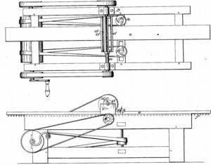
Remarks. The machine for which this patent was obtained, is in actual operation, and executes good work. We have seen a piece of cross grained white pine plank, which had been planed, tongued, and grooved, by it, with a finish which it would have been difficult to have given with the ordinary fore and match planes. It differs essentially from all the planing machines which we have heretofore known. The knives, or cutters, for planing, are arranged so as to form a American Patents for December, with Remarks. cylinder or drum, being attached by their ends to two circular plates. These cylinders are made to revolve with a very rapid motion, the plank, or board, being carried forward by a rack and pinion. Whilst the face is thus planed, a tongue and groove may be cut upon the edges by wheels with cutters projecting from them; the plank is is by this process brought to an exact and equal thickness. Circular saws are used to bring the plank to an equal width, or to cut it into strips. Cutters for mouldings, work on the same principle. "Said William Woodworth does not claim the invention of circular saws, or cutter wheels, knowing they have long been in use; but he claims as his invention, the improvement and application of cutter or planing wheels, to planing boards, plank, timber, or other material; also his improved method of cutters for grooving, and tongueing, and cutting mouldings in wood, stone, metal, or other material; and also for facing and dressing brick, as all the wheels may be used single, or separately, for moulding, or any other purpose before indicated. He also claims as his improved method, the application of circular saws, for reducing floor plank and other materials, to a width."
DATAMP: illustration
Illustrations from DATAMP

DATAMP (Directory of American Tool and Machinery Patents), via the Internet Archive · Archived DATAMP page
About this record
- Patentee
- DATAMP
- Date
- the Name and Date index of patents, DATAMP, USPTO records
- Invention
- DATAMP
- Listed in
- the Name and Date index of patents, DATAMP, USPTO records, Jim Shaw's X-patent list, the Journal of the Franklin Institute, Burke's List of Patents (1847)
- Burke's 1847 Patent Office list gives the same patent.