

Drawings and documents
National Archives restored drawings: drawing
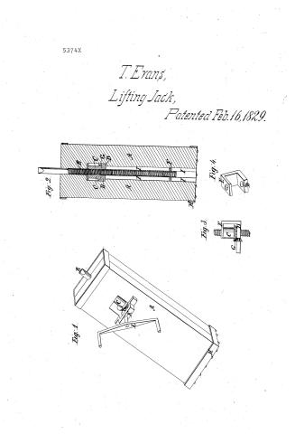
Thomas Evans' Patent Drawing for a Jack Screw

National Archives, Restored Patent Drawings (Record Group 241) · Full-size scan at the National Archives · Catalog record
Show the text on the drawing Hide (103 words)
Words on the drawing as machine-read by the National Archives; not checked. Useful mainly for searching.
57. HOISTING. / Lifting-Jacks, / Thomas Cvans Eintered. / Vol.8.7,401, / Screw. / 054 6514 / 5374-+ / Jack Perew, / - - Patented Feb16,1829. / Fid 2 / Fig.1. / DEL / Fig^3 / N10 / Fight / Fig.1, JackSerew, References. Eig.2, Section, / Patent offine 20% 1841. / Figh3. beveled gearing' detatched, / FigH. iron seat plates, / Made under the dirition of the / 11 A. stock. B. dagger. C.female screw. / Saturbinecuformity with Out of Cougrep 3 March 1834, / Dlower seat plate, E. uper seatplate, / E.key. G,bevel gear, II lower band with projections / I. groovefor key to workin. K. support of bevel wheel. / I crank / Herryh Ellmooth / Commissioner of Patents,
USPTO scan
The patent as scanned by the USPTO
-
 Page 1
-
 Page 2


U.S. Patent and Trademark Office · Google Patents
Show the transcription Hide (130 words)
Machine transcription (LightOnOCR) of the pages as scanned by the USPTO, most of them the handwritten copies made when the records were restored after the 1836 fire. Not checked; it can misread handwriting, so compare it with the scan.
Page 1.
5374X
T. Evans,
Lifting Jack,
Patented Feb. 16, 1829.
Fig. 1.
Fig. 2.
Fig. 3.
Fig. 4.
Page 2.
United States Patent Office
PTO - BOYERS, PA Duty Station
MISSING PAGE TEMPORARY NOTICE
PATENT # 5374X FOR ISSUE DATE 2-16-1829
HAS BEEN SCANNED, BUT WITH MISSING PAGE(S). UPON RECEIVING OF MISSING PAGE(S), THE ENTIRE DOCUMENT WILL BE RESCANNED.
PLEASE CALL IMAGE DATA ADMINISTRATION STAFF OF 557-6154 IF YOU HAVE A QUESTION. ASK FOR DAVE GROOMS, ANITA YOUNG OR POLA JONES.
THIS NOTICE IS FOR THE MISSING PAGE CONTAINING:
COLUMN # All Text
Data Conversion Operation
Boyers, Pa
Published accounts: specification
Specification printed in the Journal of the Franklin Institute
Journal of the Franklin Institute, new ser., vol. 6 (1830), p. 160 · View the page
Text of the specification as printed in the Journal, from OCR; not proofread.
Specification of a patent for a machine for Lifting Ships or Vessels out of the Water. Granted to WILLIAM BALLARD, of New York, as assignee of the inventor, THOMAS EVANS, of the City of New York, May 28, 1830. THE invention above mentioned consists in the application or substitution of cylinders with floating pistons in them in place of screws, or other machinery, in the vertical lift docks now in use. These cylinders with their pistons are constructed in precisely the same manner as what is known and called Bramah's hydrostatic, or water press, and are applied to the lifting of ships in the following manner, to wit; such a number of piles are driven in the river, as to form two piers at such distance apart as to allow a ship to be floated in between them; those piles which form the inner row of those piers, are driven at regular distances asunder, and are firmly secured together by large pieces of timber called plate pieces, running the Evans' machine for Lifting Ships. whole length of the dock, on each side, level, or even with the surface, or decks of the piers. Between these piles, and from said plates, are suspended a row of cast iron cylinders at equal distances apart, and directly opposite each other, on either side of the dock. Each of these cylinders is furnished with a solid iron piston, sliding through a stuffing box in the head of the cylinder; each piston has a cross head, fitted on its upper end, reaching to square posts framed into the plate, half way between the cylinders. These posts form guides for the cross heads, causing them and the piston to which they are connected, to move perpendicularly to the cylinders. From the cross heads iron bars are suspended on either side of each piston, reaching down through the plates to the trussed beams, or girders, which form the cradle for supporting the ship. These bars pass through the ends of the beams aforesaid, and are strongly secured to them by iron keys passed through the bars on the under side of the beams. These beams are made of great strength by a peculiar method of trussing them; they reach the whole width of the dock, two to each pair of cylinders forming a section; a number of sections forming the cradle; the length, breadth and strength of which will depend on the size of the ship to be lifted. Each section moves independent of the rest, and can be raised or lowered at pleasure. The cylinders are connected together on each side of the dock by a pipe running the whole length thereof. In these pipes, betweeneach cylinder, there is a stop cock, shutting off the communication between them when necessary. One or more pumps are attached to these pipes for the purpose of forcing water into the cylinders for raising the ship. Other stop cocks are provided for letting the water out of the cylinders when the ship is to be lowered. Operation. The water being let out of the cylinders by turning the cocks aforesaid, the pistons by their weight settle down in the cylinders, carrying the cradle along with them; and when the pistons are wholly within, the cradle is sunk low enough beneath the surface of the water to allow the ship to be floated in between the piers, and over the cradle; she being moored in the centre between said piers, her keel is directly over the keel blocks. The pumps being now set at work, the cradle is raised till the sections have all found their bearings. The bilge wedges are now hove up to steady the ship in her position. She is now lifted some distance further, when being safely shored, she is by the continued action of the pumps safely and expeditiously lifted out of the water. The lowering of the ship is a work of great simplicity; a number of escape cocks on each side of the dock are opened and she descends by her own weight with a steady, constant motion, till she finds her bearing in the water. Now I wish to be understood that what I claim as new and my invention, is the application of what is called the hydrostatic principle of forcing water into cylinders, after the manner of what is known as Bramah's press; the raising of the pistons by the injection of water into the cylinders in which they are inserted, being applied to lifting the ship in the manner described above. And further, be it VOL. VI. No. 3. - SEPTEMBER, 1830. 21 known that I do not confine myself to the particular manner of application as described above; that only appearing the most convenient at present. T. EVANS. FOR THE JOURNAL OF THE FRANKLIN INSTITUTE. Remarks upon Mr. CHARLES P. SAKMEISTER's patent for improvements on the Piano Forte. TO THE EDITOR. SIR,-As you appear to desire to elicit truth in your examination of patented inventions I am induced to offer a few remarks upon one issued on the 14th of May last, to Mr. C. P. Sakmeister, of New York, for improvements in piano fortes. Having had an opportunity of examining the specification and drawings, explaining the so called improvements, and claiming some knowledge upon the points to which they relate, you, perhaps, may not deem my remarks impertinent. Mr. S. claims, in his specification, three improvements, the first the introduction of a lever check to prevent the reverberation of the hammer. Secondly, a lever upon which the front catch is placed, and the manner in which it is made to act upon the hammer. Thirdly, the shape of the hammer, of the inverted action, (as practised by the Germans.) With respect to the first, I witnessed the same thing in the manufactory of Messrs. Loud & Brothers, of this city, three or four years since; the action then made by them was so similar to that described by Mr. S. that had it been made since his patent was obtained, any one upon examination would at once declare that his plans had been copied from it; they are, in fact, alike in the lever and its attachments, and in the mode of its operation in every important particular, (I speak of its application to the English action.) The front catch is merely an inversion of the other, its principle being the same. I am convinced, however, that in practice, whatever advantages it might have offered were more than counterbalanced by its defects, as the Messrs. Loud do not continue to use it. Its complexity probably subjected it to frequent derangement. The simple check attached to the key, is, upon the whole, certainly preferable, as by the very easy contrivance of taking off the top part of the action, the key can be taken out. With respect to the shape of the hammer, one exactly similar to it was formerly used by Mr. Albrecht, of this city, and it is believed that it had been previously employed by other makers. These remarks, sir, are not invidiously made; the writer would hail with pleasure any real improvement in his business, by whomsoever introduced. The gentleman who has taken the patent, may, like many others, have stumbled upon something which he may have supposed to be new, but which appears fairly to belong to your class of modern antiques. A MANUFACTURER. Philadelphia, August 10th, 1830. Notice respecting the Mortising Machines patented by Mr. JOHN M'CLINTIC, of Chambersburg, Pennsylvania, in 1827, and by Mr. ABNER FOSTER, of Phillipston, Massachusetts, in 1830. Extracted from a letter to the Editor from the former gentleman. SIR,-In examining the number of your very valuable Journal for the present month, I find that mention is made of an improvement in the mode of mortising, in various kinds of joiner's work, for which a patent was obtained by Mr. Abner Foster, in April last. You remark that the machine is very clearly described, and very perfectly represented in the drawing, and that in its general structure it resembles the machine patented by me in October, 1827. You very correctly state that in mine the chisels are brought down and raised by means of a lever moved by hand. In Mr. Foster's improvement it appears that the levers used are called treadles, as they are operated upon by the foot, and that the chisels are elevated by spring poles. The only parts claimed, are, you say, "the springs and the treadles, and their application to the purpose of mortising." Upon examining my specification, it will be seen that even in these particulars Mr. Foster has been anticipated by me. The following words will be found in it: "the gate, or part which holds the chisels, may be worked by treadle and spring, to raise the gate." Independently, therefore, of the general structure of the machine being similar to mine, it will be at once evident that in the points specifically claimed by Mr. Foster, the ground had been clearly and distinctly pre-occupied by me. To one who has manifested so much zeal for the diffusion of correct information on the useful arts, I need make no apology for the trouble I now give. Yours, &c. Chambersburg, Pennsylvania, July 31, 1830. ENGLISH PATENTS. JOHN M'CLINTIC. TO WILLIAM GODFREY KNELLER, Chemist, for certain improvements in Evaporating Sugar, which improvements are also applicable to other purposes. Dated May 27, 1829. I, the said William Godfrey Kneller, do hereby declare that my invention consists in a method or process, and certain apparatus as hereinafter described, by which I am enabled to evaporate liquids and solutions at a low temperature, and thereby to avoid the injury to which certain substances which require a nice and delicate application of heat, such as sugar, for instance, are liable to, by being exposed to too high a temperature. And I do further declare that my said invention and improvements consist in forcing, by means of bellows, or any other blowing apparatus, atmospheric or any other air, either in a hot or cold state, through the liquid or solution subjected to evaporation; and this I do by means of pipes, whose extremities reach nearly (or within such distance as may be found most suitable under peculiar circumstances,) to the upper or interior area of the bottom of the pan or boiler containing such liquid or solution, the other extremities of such pipes being connected with larger pipes which communicate with the bellows or other blowing apparatus, which forces the air into them. The pan or boiler may be of any shape or dimensions, but I prefer it with a flat level bottom, and I introduce the liquid or solution to the depth of from about four to six inches. The heat may be applied to the lower or exterior area of the bottom of such pan or boiler by naked fire, steam, or hot air, in the usual manner, and by means well understood; the air then forced into the heated liquid or solution keeps it in a constant agitation, abstracts its heat, and carries off the steam or vapour which is to be expelled. By raising the degree of heat under the pan or boiler, and increasing the quantity and velocity of the air injected into the liquid or solution, or on the contrary, by lowering the heat and moderating the injection of air, the evaporation is accelerated or retarded at the pleasure of the operator, according to the nature of the substances or the effect desired. And I do further declare that in applying this my said invention and improvements to the evaporation of cane juice or sirop for making refined sugar, I can bring it to the proof or crystallizing point by keeping the temperature of such sirop, or cane juice, between one hundred and forty, and one hundred and seventy degrees of Fahrenheit's thermometer, although I prefer to keep it between one hundred and sixty, and one hundred and seventy degrees. By this simple and cheap apparatus I obtain a great quantity of large and shining crystals, which hitherto were attainable only by evaporating in vacuo, a very troublesome and expensive process, while other methods, by exposing the sugar to a high temperature, impair the quantity, size, and brilliancy of the crystals, and form a great quantity of molasses or treacle. And I further declare that these my invention and improvements can be applied to the evaporation of other liquids and solutions, as well as sirops and cane juice, or sugar, by varying the apparatus and the degree of temperature according to their nature and the will of the operator. And I further declare that these my invention and improvements can also be applied to distilling or rectifying spirits, provided that a vent be given to the air arising with the spirit after the latter shall be condensed. And I further declare, that in order more quickly to remove the steam or vapour from the surface of the liquid or solution, and thereby to favour the evaporation, I sometimes, and particularly when I use hot air for heating the pan or boiler, conduct the hot air, after it has given out part of the heat to the bottom of the boiler, to the surface of the liquor or solution, but I do not consider this contrivance necessary in any, nor adviseable in all cases. It is hardly necessary to observe, that the evaporating power is augmented by increasing the diameter of the pipes, and the quantity of air propelled by the blowing apparatus through the liquid. And I do further declare, that as it is desirable that the liquid to be evaporated should be of equal depth in every part of the evaporator, the bottom of which is recommended to be perfectly level; it will be found that the liquid when sufficiently evaporated and concentrated, does not readily flow out through the spout opened for the purpose; to remedy this inconvenience, I place a vertical sliding plate from four and a half to five inches in height, and somewhat less in length than the breadth of the evaporator or pan, such plate being kept in its upright position by projections at right angles with its lower edge, which must slide as nearly as possible in contact with the bottom of the same pan. This plate is in the first instance put at that end of the pan, or evaporator, which is opposite to where the spout is situated. When the evaporation is effected to a sufficient degree, I damp the fire, or shut off the steam or hot air, and open the spout to draw off the liquid, a great part of which will immediately flow out; I then by means of a winch, or lever, raise the pipes about six inches, and gently draw the said vertical plate by a thin wire or chain towards the spout, and thus quickly clean the bottom of the pan. It is necessary to raise the pipes in order that the before mentioned plate may pass under them, and at the same time not interrupt the blast of air through the small pipes, which might be obstructed if any of the evaporated liquid should congeal or crystallize in them by cooling. For effecting these objects the main pipe arising from the bellows or blowing apparatus, is inserted into the main pipe in the evaporator, in an air tight manner, but with a joint or flexible tube sufficiently long to allow the system of blowing pipes to slide upwards for about six inches. The form and construction of the apparatus which I use to produce the above effect, may be varied according to circumstances, and the form and position of the pan or evaporating vessel to which it is to be applied. But two things are essential in its construction, the first of which is, that however numerous the blowing pipes may be, that their lower orifices should be distributed as evenly and equally over the whole surface of the bottom of the pan as possible, and secondly, that a stream of air should issue from the lower end of every one of them at the same time. To insure this latter object it is immaterial whether the bottom of the pan or boiler be perfectly level, but it is quite necessary that all the lower ends of the blowing tubes should be on a level and parallel to the surface of the fluid to be evaporated, in order that there may not be a higher column of fluid in one tube than in another. The mode of construction necessary to produce these objects may be various, but in order the more distinctly to explain my meaning and my mode of operating, I hereunto subjoin a drawing of the apparatus which I have used, and find to answer the purpose, and in which A, A, A, A, Fig. 1,* is a plan or bird's eye view of an oblong pan or boiler, B, B, B the tinned copper, or other large air pipes, which are closed at their end, C, C, C, but open into each other, and likewise into the still larger perpendicular pipe D, from which the air is e e Fig. 1. A e e e A e e D e B A e e e e e A supplied by communicating as aforesaid, to bellows or other blowing machinery; e, e, e, e, &c. are the small lateral pipes which communicate with the large air pipes, and proceed downwards through the fluid to be evaporated, to very near the bottom of the pan. The lower ends, e, e, &c. of these pipes are all very nearly equi-distant from each other, to produce the equal distribution of air before mentioned. Fig. 2, is a transverse section of the pan, A, A, A, A, Fig. 1, Fig. 2. e e e A K * In the original drawing the boiler is represented as extending to about three times the length seen in Figs. 1 and 3, the middle being omitted, as it is merely a repetition of parts similar to those shown. showing the great air pipe D, the cross pipe and its continuations B, B, B, in section, and the small descending pipes e, e, e, e, &c. as shown in the last figure, likewise the pipes f, f, f, f, which likewise descend from the pipes B, B, but in a more nearly vertical direction, which prevents their being seen in the view, Fig. 1, but by. means of which, the distances of the lower ends of these blowing tubes are brought to the same distance as under the pipes B, B, as in other parts of the pan. g, g, g, are legs to support the above described system of pipes, by standing on the bottom of the pan, and are of such length as will just prevent the lower ends of the said blowing pipes from touching it. The whole of this system of pipes is to be raised at once, as before mentioned, by any adequate machinery, in order to permit the scraping or cleaning plate, h, h, to pass under the ends of the before mentioned small blowing pipes. Fig. 3 is a longitudinal section of Fig. 1, of which a particular description will be unnecessary, as the same letters of reference denote the same parts in this and the other figures, the insertions of the small blowing pipes into the pipes B, B, being shown by black dots. In A Fig. 3. B K e e D A K e all these, Fig. 1 shows the situation near which the discharging valve or orifice should be placed, and K, K, is the line near which the surface of the fluid should stand when first introduced to be evaporated. As before mentioned, the form of this apparatus may be varied, provided its essential properties of the air blowing through all the descending tubes, and this being so disposed as to produce greatly divided and equally distributed currents of air over the whole bottom of the vessel at once, are maintained, because my invention consists in producing rapid evaporation at lower temperatures than usual, by the means hereinbefore described. OBS. It is well known that a current of air promotes evaporation, and is in many instances employed for that purpose by being made to pass over the surface of liquids; the principle on which the foregoing patent is founded, consists in forcing air through liquids, and we are inclined to think it will prove more efficient, inasmuch as the air is not only brought into intimate contact with many, and constantly changing surfaces of the liquid, but also strongly and incessantly agitates it; the effect of such a
Published accounts: journal notice
Notice in the monthly list of patents, with remarks
Journal of the Franklin Institute, new ser., vol. 3 (1829), p. 339 · View the page
15. For improvements in the machines called Jacks, or Jack Screws, used for stowing goods in ships' holds, raising heavy weights, &c.; Thomas Evans, New York, February 16.
Remarks. The common Jack, operates by means of a rack and pinion; the improved Jack, which the inventor calls Evans's improved American Jack Screw, consists, mainly, of a screw and nut, and two bevelled wheels, and appears to us to be a manifest improvement. The stock consists of two pieces of timber, divided longitudinally, and bolted together; it is usually made three feet eight inches long, ten inches wide, and five thick. An iron screw, three feet six inches long, is contained within it, and forms the dagger of the Jack. A nut, or female screw, is inserted towards the upper part of the stock, which is there strengthened and secured by iron boxes, or plates. The nut has a bevelled wheel cast upon it, which is turned by a bevelled pinion, fitted into the iron box; the squared end of the axis of this pinion, receives the lever which is to raise the screw. The male screw is kept from turning by a bolt, or pin, passed through and projecting from its lower end, and sliding in longitudinal grooves in the stock. The patentee says, "What I claim as new, and my invention, in the above described machine, is the application of bevelled wheels to cause the female screw to rotate; and likewise the method of preventing the male screw, or dagger, from turning, when in operation, by means of a key sliding in the groove on each side of the hole in the stock, as above described." A screw jack is described in Nicholson's Operative Mechanic, but certainly very inferior to the foregoing.
About this record
- Patentee
- the Journal of the Franklin Institute, Journal
- Date
- the Name and Date index of patents, USPTO records, Jim Shaw's X-patent list
- Invention
- the Name and Date index of patents
- Listed in
- the Name and Date index of patents, USPTO records, Jim Shaw's X-patent list, the Journal of the Franklin Institute, Burke's List of Patents (1847)
- The patentee's full name comes from the Franklin Institute's journal.
- Burke's 1847 Patent Office list gives the same patent.