

Drawings and documents
USPTO scan
The patent as scanned by the USPTO
-
 Page 1
-
 Page 2
-
 Page 3
-
 Page 4


U.S. Patent and Trademark Office · Google Patents
Show the transcription Hide (724 words)
Machine transcription (LightOnOCR) of the pages as scanned by the USPTO, most of them the handwritten copies made when the records were restored after the 1836 fire. Not checked; it can misread handwriting, so compare it with the scan.
Page 2.
United States Patent
Patent No.: X5379
Notice to Patentee
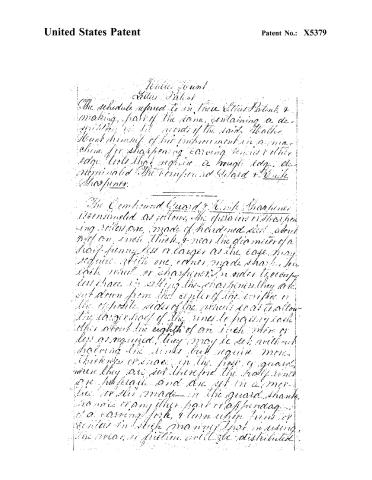
The schedule referred to in these Letters Patent, & making, part of the same, containing a description of the said "Molder" & "Hound" himself of his improvement in a machine for sharpening carving knives & other edge tools that require a hinged edge, designated "The Compound Guard & Knife Sharpening."
The Compound Guard & Knife Sharpening is constructed as follows: The operation of sharpening knives, made of hardened steel, about 1/4" or 1/2" thick, & near the diameter of a half-penny, less or larger as the case may require, with one corner made sharp, for each wheel or sharpening, in order to occupy less space in setting the sharpeners, they are cut down from the center of the wheel to the opposite sides of the wheel so as to allow the longer half of the rims to pass each other about the eighth of an inch, more or less as required. They may be set without shaving the rims, but require more thickness or space in the part of guard, where they are set, therefore the half rims are hollowed and are set in a manner or slot made in the guard, shank, handle or any other part or off-joining, of a carving fork, & turn which turns or centers in such manner that in using, the wear or friction will be distributed.
Page 3.
United States Patent
Patent No.: X5379
around the whole circumference of the sharpening fork. Where the "sharpening stones" are set in forks made for the machine, they form a "Guard & Sharpeners" being set in the neck of the fork which may be conveniently used or located on the table where the stones are set up. In order to set them to advantage in the common carving fork, the old guard may be removed, and a new one made of suitable thickness to receive the sharpeners on an oblong, round, etc. cut through the same, supported upon each with the lines as indicated, parallel passing each other. This mode of putting or attaching the sharpeners to the "carving fork" instead of a stand, or other appendage, for lack, use is through portable, as it is always at hand, when wanted in the act of carving, & the knife becoming suddenly dull, which often occurs, the edge can be instantly restored, without drawing the fork from its place, by having the edge of the knife between the sharpeners or lute. If not they are set in the guard, in order to hold the sharpeners firm, push down the guard, with the back of the carving knife raising it with the same, when necessary. For sharpening Butcher knives & other knives where the fork is not wanted, the sharpeners may be set in a stand, holder or handle, fixed in a stand, bench or otherwise as may be required, & suspended upon center as in the fork.
The manner of setting it in the fork is the same, as a handle or fork, they must be held
Page 4.
United States Patent
Patent No.: X5379
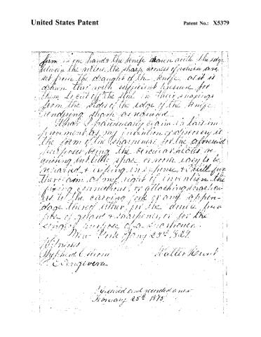
form in one hand the knife drawn with the edge between the fingers, the sharp corners of which are set from the draught of the knife, as it is drawn, thus with sufficient pressure for them to cut off the steel in their shavings from the sides of the edge of the knife, rendering sharp as required.
What I particularly claim in this improvement as my invention or discovery is the form of the sharpeners for the aforesaid purposes being the circular holes requiring but little space or room, easy to be operated, & referring in a sense, & still further claim as my right of invention the fixing connections, or attaching sharpeners to the carrying fork or any apparatus therefor either for the double purpose of sharpening & sharpening, or for the single purpose of a sharpening.
New York, Jan 23rd, 1877
Witness
Shepherd C. Martin
C. D. Anguera
Halter H. Hunt
Recorded and recorded on
February 25th 1877
Published accounts: journal notice
Notice in the monthly list of patents, with remarks
Journal of the Franklin Institute, new ser., vol. 3 (1829), p. 341 · View the page
20. For a machine for Sharpening Carving Knives, and other tools that require a rough edge; denominated the "Compound Guard, and Knife Sharpener;" Walter Hunt, New York, February 19.
Remarks. This sharpener consists of two small wheels of hard steel, turning upon centre pins, and so placed that their peripheries intersect each other. The knife to be sharpened is drawn across between these two disks, by which means it readily obtains a fine cutting edge. We have one of them in use, and find it to answer the intention perfectly. A machine somewhat similar has been patented in England, and many of them imported into this country. These consisted of two long rollers or cylinders of steel, so turned in ridges and hollows, as to allow the ridges reciprocally to interlock, or intersect; between, and along these, the knife is drawn. In most instances, the two rollers used by Mr. Hunt, are fixed within cheeks formed in the guard of the carving fork. The claim is in the following words:-"What I particularly claim in this imA, represents a pulley of 18 inches diameter, with the axle and handle, or winch. The centre of this pulley is placed about three feet above the platform of the well, or surface of the ground. It has high edges to prevent the bands from slipping off. There is a pulley at the bottom of the well, like the above in every respect, except that it has no handle. It serves to guide the band, and is placed within a few inches of the bottom of the well. c, c, a band of sheet tin 34 inches wide; the length of course depends on the depth of the well, and, it necessarily follows, that if the same number of buckets are used, they will be farther from, or nearer to, each other, according to the depth of the well. d, d, d, d, &c. tin buckets made square, containing a quart each. They are of the same width as the band, and attached to it by 2 knees, that pass d A C C fd Id d under the band and up the side of the buckets. There are 24 buckets, placed at equal distances, which number of buckets may be used for any pump for domestic purposes, be the well of greater or less depth. This will equalize the power to raise water from any depth, by making the water delivered in a given time in the inverse ratio of the depth of the well; that is, but of the water will be delivered by the same power in the same time from a well of 100 feet deep, that will be raised from a well of 25 feet by the same power, in the same time. E, is the spout, that receives the water; it is placed on the side of the pulley at right angles with its axis. f, &c. the cogs, continued all round the inner surface of the band, at about 9 inches apart, or exactly of the periphery of the pullies; they are placed in the middle, and are half its width. They are made of sheet tin soldered on; as their office is only to keep the bands from slipping, they will never wear. They fall into grooves made at corresponding distances on the periphery of the pulley. I made my experimental pump to the above plan, and of the dimensions and materials there specified, and it answers very well.
About this record
- Patentee
- the Journal of the Franklin Institute, Journal
- Date
- the Name and Date index of patents, USPTO records, Jim Shaw's X-patent list
- Invention
- the Name and Date index of patents
- Listed in
- the Name and Date index of patents, USPTO records, Jim Shaw's X-patent list, the Journal of the Franklin Institute, Burke's List of Patents (1847)
- The patentee's full name comes from the Franklin Institute's journal.
- The residence comes from the Franklin Institute's journal.
- Burke's 1847 Patent Office list gives the same patent.