

Drawings and documents
National Archives restored drawings: drawing
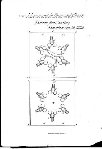
J. Leonard, Jr., J. S. Brainard, and A. Sizer's Patent Drawing for Patterns for Casting

National Archives, Restored Patent Drawings (Record Group 241) · Full-size scan at the National Archives · Catalog record
Show the text on the drawing Hide (63 words)
Words on the drawing as machine-read by the National Archives; not checked. Useful mainly for searching.
lolding / PATTERNS FOR CASTING. / Patents Vol.10, page 107- no number / Patented 28th Jan Y 18 18 / $1.00 / Patteries for Casting I'm 1 Bruss, / 1830 / J.LeonavelJr; J.S.Brainard, and A. Sizers / A. / 2. / 08 / CLASSIFICATION / 5799-+ / DIVISION / 7 6 / - pattim plan / 90 / with kids patte / the cark sir / 7] / 5. / Cent in a from / 08 / 4. / 3. / B. / 2. / 08 / 20 / og / 08 / 08. / 3.
USPTO scan
The patent as scanned by the USPTO
-
 Page 1
-
 Page 2
-
 Page 3
-
 Page 4
-
 Page 5


U.S. Patent and Trademark Office · Google Patents
Show the transcription Hide (1,486 words)
Machine transcription (LightOnOCR) of the pages as scanned by the USPTO, most of them the handwritten copies made when the records were restored after the 1836 fire. Not checked; it can misread handwriting, so compare it with the scan.
Page 1.
5799X J. Leonard, Jr., Brainard & Siver,
Pattern for Casting.
Patented Jan. 28, 1830.


Page 2.
Jan. 28, 1830
Jonathan Leonard and Jared S. Brainard & Amasa Fizer
X5799 Letters Patent.
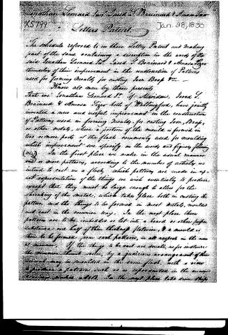
The schedule referred to in these Letters Patent and making part of the same containing a description in the words of the said Jonathan Leonard and Jared S. Brainard & Amasa Fizer themselves of their improvement in the construction of Patterns used for forming Moulds for casting Iron, Brass &c.
Know all men by these presents,
That we Jonathan Leonard Sr. of Meriden, Jared S. Brainard & Amasa Fizer both of Wallingford, have jointly invented a new and useful improvement in the construction of Patterns used in forming Moulds for casting Iron, Brass, or other metals, where a portion of the mould is formed in two or more parts of the flask commonly used for moulding which improvement we specify in the words and figures following (viz.) In the first place we make in the usual manner one or more patterns, according to the number of articles we intend to cast in a flask, which patterns are made in exact representation of the things we wish eventually to produce except that they must be large enough to allow for the shrinking of the metal, which takes place both in casting the pattern and the things to be formed in most metals, moulded and cast in the common way. In the next place these patterns are to be imbedded or let into a board or other proper substance one half of their thickness flatwise, & a mould is then to be formed from each pattern, in all respects in the usual manner. If the things to be cast are small, as for instance the common thumb screw, by a judicious arrangement of the several may be moulded in the same flask, with a view to produce a pattern, such as is represented in the annexed drawings, number 1, 2, 3. In the next place take some strips
Page 3.
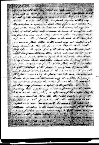
of wood or other substance about one inch wide, and one-eighth of an inch in thickness, so as thick as the plate represents in each of each of the openings is wanted to be 8 of such length and number so that when they are formed together at their ends they will form a square or such other figure as is needed as large as the said plate is intended to be made; the size and shape of which plate will of course be made to correspond with the flask to be used in moulding from the plate and pattern attached to the same. Then place the frame on the sand in the lower part of a common flask, fill in the usual way and mould as already directed so that the frame will keep the metal within itself & place the upper part of the flask upon the lower part with the frame between them which will keep the two parts asunder a small distance equal to its thickness. Some small pieces of some hard substance should also be placed between the outer parts of each portion of the flask, which pieces should be of the thickness of the frame & are of use to prevent the weight which is to be placed in the usual manner upon the flask from imbedding the frame into the sand. The sprue hole should be formed in the usual way at a little distance from the mould to prevent the metal from washing the moulds & in that way produce a defect in the pattern. It will be necessary that a gate way should be formed for each pattern & cast at the same time, or afterwards placed upon the plate and care must be taken, that the metal should be of a proper temperature when poured in, that the work may be as perfect as it can conveniently be made. The plate and patterns attached to the same being now cast, should be taken out and finished in the usual way, & if the object is to form a plate with patterns attached for casting them separately, as at a time, the same is illustrated by the manner shown in Fig. 9. The plate when thus finished must have two or more holes made, that the same of separate pieces can be separated.
Page 4.
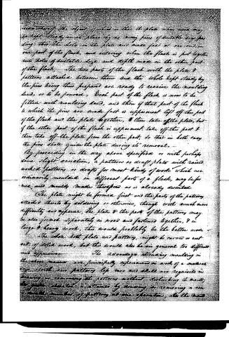
side thereof, the object of which is that the plate when used may be kept steady in its place by as many pins of suitable size passing through the holes in the plate and made fast at one end, in one part of the flask, and entering when the flask is put together into holes of suitable size and depth made in the other part of the flask. The two parts of the flask with the plate & patterns attached between them and the whole kept steady by the pins being thus prepared are ready to receive the moulding sand, or to be poured. Each part of the flask is now to be filled with moulding sand, and then if that part of the flask to which the pins are made fast is uppermost lift off the part of the flask and the plate together, & then take off the plate, but if the other part of the flask is uppermost, take off the part & then take off the plate from the other part, so that in both cases the pins shall guide the plate during its removal.
By proceeding in the way above specified or with perhaps some slight variation, a pattern or draft plate with raised worked patterns or drafts for most kinds of work which are ordinarily moulded in different parts of a flask, may be formed, and moulds made therefrom as is already described.
The plate might be formed first and the parts of the patterns attached thereto by soldering or otherwise, though with much more difficulty and expense. The plate & the parts of the patterns may be also formed separately in wood and fastened together, & in large & heavy work, this would probably be the better mode.
The whole both plate and patterns, might be carved or cut out of solid wood, but this would also be in general too difficult and expensive.
The advantages attending moulding in the above manner are principally experienced in work of a moderate size, with our patterns left once and shall are requisite in drawing or removing the patterns without disturbing the mould; the greater advantage is attained by drawing or removing a considerable number of patterns at one operation, also the sand
Page 5.
No. 13799
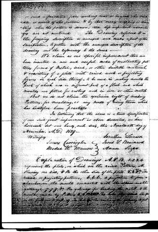
in such a specimen from working over or beyond the width or width of the pattern & by that means crippling or ruining when the pattern is drawn, other less important advantages are not mentioned. The Drawing referred to in the foregoing description is annexed and makes a part of this specification, together with the annexed description of the drawing and the reference to the same.
We claim as our specific improvement that we have invented a new and useful mode of constructing patterns, formed of metal, wood, or other suitable material, & consisting of a plate with raised work or projecting figures on each side thereof, to be used in making moulds the parts of which are in different parts of a flask and which moulds are fitted for casting work in iron or other metal. But we do not claim the exclusive right of making Patterns, for moulding, or any mode of using them which has heretofore been practiced.
In testimony that the above is a true specification of our said joint improvement as above described, we have hereunto set our hands and seals, this Nineteenth day of November, A.D. 1829.
Witness
Jonathan Leonard
James Carrington & Jared S. Brainard
Medard M. Munson & Amasa Siger
Explanation of Drawings A, B, 1, 2, 3, 4 represents the plate, on which are the raised Patterns, A. Showing one side, & B. the other side of the plate. 3, 3, 3, the raised or projecting patterns, 6, 6, 6, a projection to form a stander, in the mould connected with the flange and the gateways, 7, 7, 7, 8, the gateway for leading the metal to the moulds, made by Pattern 5, 5, 5, 5, 5, the holes through which the metal is led, 9, 9, 9, the holes for the vents of the gateway to let in …
Published accounts: journal notice
Notice in the monthly list of patents, with remarks
Journal of the Franklin Institute, new ser., vol. 5 (1830), p. 228 · View the page
131. For constructing Patterns of Metal, Wood, or other Material, to be used as Moulds for Casting; Jonathan Leonard, jr., of Meriden, Jareel, S. Brainard, and Amasa Sizer, of Wallingford, New Haven county, Connecticut, January 28.
Remarks. The invention claimed to have been made by the patentees, is, "a new and useful mode of constructing patterns formed of metal, wood, or other suitable material, and consisting of a plate with raised work, or projecting figures on each side thereof, to be used in making moulds, the parts of which are in different parts of a flask, and which moulds are fitted for casting work in iron, or other metal. But we do not claim the exclusive right of making patterns for moulding, or any mode of using them which has heretofore been practised." It has been a common practice in moulding spikes for ships, and many other articles which are to be cast in great numbers, to fix onehalf of the patterns on one mould board, and the corresponding halves upon another, so as to mould upon the principle above pointed out. Metal plates with one-half the pattern on each side have also been used, and a patent obtained for them. A particular account of this will be found in our list of patents for March, 1829, at page 419 of vol. 3, new series.
About this record
- Patentee
- DATAMP
- Date
- the Name and Date index of patents, DATAMP, USPTO records
- Invention
- DATAMP
- Listed in
- the Name and Date index of patents, DATAMP, USPTO records, Jim Shaw's X-patent list, the Journal of the Franklin Institute, Burke's List of Patents (1847)
- Burke's 1847 Patent Office list gives the same patent.